
SHIGLEY'S MECH.ENGIN....(LOOSE)>CUSTOM<
10th Edition
ISBN: 9781260163155
Author: BUDYNAS
Publisher: MCG CUSTOM
expand_more
expand_more
format_list_bulleted
Concept explainers
Videos
Textbook Question
Chapter 4, Problem 97P
The figure shows a
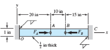
Problem 4–97
Expert Solution & Answer
Want to see the full answer?
Check out a sample textbook solution
Chapter 4 Solutions
SHIGLEY'S MECH.ENGIN....(LOOSE)>CUSTOM<
Ch. 4 - The figure shows a torsion bar OA fixed at O,...Ch. 4 - For Prob. 41, if the simple support at point A...Ch. 4 - A torsion-bar spring consists of a prismatic bar,...Ch. 4 - An engineer is forced by geometric considerations...Ch. 4 - A bar in tension has a circular cross section and...Ch. 4 - Prob. 6PCh. 4 - Prob. 7PCh. 4 - Derive the equations given for beam 2 in Table A9...Ch. 4 - Derive the equations given for beam 5 in Table A9...Ch. 4 - The figure shows a cantilever consisting of steel...
Ch. 4 - A simply supported beam loaded by two forces is...Ch. 4 - Using superposition, find the deflection of the...Ch. 4 - A rectangular steel bar supports the two...Ch. 4 - An aluminum tube with outside diameter of 2 in and...Ch. 4 - The cantilever shown in the figure consists of two...Ch. 4 - Using superposition for the bar shown, determine...Ch. 4 - A simply supported beam has a concentrated moment...Ch. 4 - Prob. 18PCh. 4 - Using the results of Prob. 418, use superposition...Ch. 4 - Prob. 20PCh. 4 - Consider the uniformly loaded simply supported...Ch. 4 - Prob. 22PCh. 4 - Prob. 23PCh. 4 - Prob. 24PCh. 4 - Prob. 25PCh. 4 - Prob. 26PCh. 4 - Prob. 27PCh. 4 - Prob. 28PCh. 4 - 429 to 434 For the steel countershaft specified in...Ch. 4 - Prob. 30PCh. 4 - Prob. 31PCh. 4 - Prob. 32PCh. 4 - For the steel countershaft specified in the table,...Ch. 4 - For the steel countershaft specified in the table,...Ch. 4 - Prob. 35PCh. 4 - Prob. 36PCh. 4 - Prob. 37PCh. 4 - Prob. 38PCh. 4 - Prob. 39PCh. 4 - Prob. 40PCh. 4 - The cantilevered handle in the figure is made from...Ch. 4 - Prob. 42PCh. 4 - The cantilevered handle in Prob. 384, p. 154, is...Ch. 4 - A flat-bed trailer is to be designed with a...Ch. 4 - The designer of a shaft usually has a slope...Ch. 4 - Prob. 46PCh. 4 - If the diameter of the steel beam shown is 1.25...Ch. 4 - For the beam of Prob. 4-47, plot the magnitude of...Ch. 4 - Prob. 49PCh. 4 - 4-50 and 4-51 The figure shows a rectangular...Ch. 4 - and 451 the ground at one end and supported by a...Ch. 4 - The figure illustrates a stepped torsion-bar...Ch. 4 - Consider the simply supported beam 5 with a center...Ch. 4 - Prob. 54PCh. 4 - Prob. 55PCh. 4 - Solve Prob. 410 using singularity functions. Use...Ch. 4 - Prob. 57PCh. 4 - Prob. 58PCh. 4 - Prob. 59PCh. 4 - Solve Prob. 413 using singularity functions. Since...Ch. 4 - Prob. 61PCh. 4 - Solve Prob. 419 using singularity functions to...Ch. 4 - Using singularity functions, write the deflection...Ch. 4 - Determine the deflection equation for the...Ch. 4 - Use Castiglianos theorem to verify the maximum...Ch. 4 - Use Castiglianos theorem to verify the maximum...Ch. 4 - Solve Prob. 415 using Castiglianos theorem.Ch. 4 - Solve Prob. 452 using Castiglianos theoremCh. 4 - Determine the deflection at midspan for the beam...Ch. 4 - Using Castiglianos theorem, determine the...Ch. 4 - Solve Prob. 441 using Castiglianos theorem. Since...Ch. 4 - Solve Prob. 442 using Castiglianos theorem.Ch. 4 - The cantilevered handle in Prob. 384 is made from...Ch. 4 - Solve Prob. 450 using Castiglianos theorem.Ch. 4 - Solve Prob. 451 using Castiglianos theorem.Ch. 4 - The steel curved bar shown has a rectangular cross...Ch. 4 - Repeat Prob. 476 to find the vertical deflection...Ch. 4 - For the curved steel beam shown. F = 6.7 kips....Ch. 4 - A steel piston ring has a mean diameter of 70 mm....Ch. 4 - For the steel wire form shown, use Castiglianos...Ch. 4 - 4-81 and 4-82 The part shown is formed from a...Ch. 4 - 4-81 and 4-82 The part shown is formed from a...Ch. 4 - Repeat Prob. 481 for the vertical deflection at...Ch. 4 - Repeat Prob. 482 for the vertical deflection at...Ch. 4 - A hook is formed from a 2-mm-diameter steel wire...Ch. 4 - The figure shows a rectangular member OB, made...Ch. 4 - Prob. 87PCh. 4 - For the wire form shown, determine the deflection...Ch. 4 - Prob. 89PCh. 4 - Prob. 90PCh. 4 - Prob. 91PCh. 4 - Prob. 92PCh. 4 - Solve Prob. 492 using Castiglianos method and...Ch. 4 - An aluminum step bar is loaded as shown. (a)...Ch. 4 - The steel shaft shown in the figure is subjected...Ch. 4 - Repeat Prob. 495 with the diameters of section OA...Ch. 4 - The figure shows a 12- by 1-in rectangular steel...Ch. 4 - For the beam shown, determine the support...Ch. 4 - Solve Prob. 498 using Castiglianos theorem and...Ch. 4 - Consider beam 13 in Table A9, but with flexible...Ch. 4 - Prob. 101PCh. 4 - The steel beam ABCD shown is simply supported at C...Ch. 4 - Prob. 103PCh. 4 - A round tubular column has outside and inside...Ch. 4 - For the conditions of Prob. 4104, show that...Ch. 4 - Link 2, shown in the figure, is 25 mm wide, has...Ch. 4 - Link 3, shown schematically in the figure, acts as...Ch. 4 - The hydraulic cylinder shown in the figure has a...Ch. 4 - The figure shows a schematic drawing of a...Ch. 4 - If drawn, a figure for this problem would resemble...Ch. 4 - Design link CD of the hand-operated toggle press...Ch. 4 - Find the maximum values of the spring force and...Ch. 4 - As shown in the figure, the weight W1 strikes W2...Ch. 4 - Part a of the figure shows a weight W mounted...
Knowledge Booster


Learn more about
Need a deep-dive on the concept behind this application? Look no further. Learn more about this topic, mechanical-engineering and related others by exploring similar questions and additional content below.Similar questions
- The plane truss shown in the figure supports vertical loads F at joint D, 2F at joint C, and 3F at joint B. Each member is a slender circular pipe (E = 70 GPa) with an outside diameter of 60 mm and wall thickness of 5 mm. Joint B is restrained against displacement perpendicular to the plane of the truss. Determine the critical value of load variable F(kN) at which member BF fails by Eu1er buckling.arrow_forwardAn idealized column is composed of rigid bars ABC and CD joined by an elastic connection with rotational stiffness ßRIat C. There is a roller support at B and an elastic support at D with translationa1 spring stiffness ß and rotational stiffness ßR2. Find the critical buckling loads for each of the two buckling modes of the column. Assume that L = 3 m, ß = 9 kN/m, and ßR]= ßR1= ßL2. Sketch the buckled mode shapes.arrow_forwardA rectangular column with cross-sectional dimensions b and h is pin-supported at ends A and C (see figure). At mid-height, the column is restrained in the plane of the figure but is free to deflect perpendicularly to the plane of the figure. Determine the ratio h/b such that the critical load is the same for buckling in the two principal planes of the column.arrow_forward
- A vertical pole of aluminum is fixed at the base and pulled at the top by a cable having a tensile force T(see figure). The cable is attached at the outer edge of a stiffened cover plate on top of the pole and makes an angle a = 20° at the point of attachment. The pole has length a = 2.5 m and a hollow circular cross section with an outer diameter d2= 280 mm and inner diameter d1= 220 mm. The circular cover plate has diameter 1.5d2 Determine the allowable tensile force Tallow in the cable if the allowable compressive stress in the aluminum pole is 90 MPa.arrow_forwardA long slender column ABC is pinned at ends A and C and compressed by an axial force F (sec figure). At the midpoint B, lateral support is provided to prevent deflection in the plane of the figure. The column is a steel wide-flange section (W 250 × 67) with E = 200 GPa. The distance between lateral supports is L = 5.5 m. Calculate the allowable load P using a factor of safety n = 2.4, taking into account the possibility of Eu 1er buckling about cither principal centroidal axis (i.e., axis 1-1 or axis 2-2).arrow_forwardA column, pinned at top and bottom, is made up of two C 6 x 13 steel shapes (see figure) that act together. Find the buckling load (kips) if the gap is zero. Find required separation distance d(inches) so that the buckling load is the same in y and z directions. Assume that E = 30,000 ksi and L = 18 ft. Note that distance d is measured between the centroids of the two C shapes.arrow_forward
- What is the maximum possible value of the clamping Force C in the jaws of the pliers shown in the figure if the ultimate shear stress in the 5-mm diameter pin is 340 MPa? What is the maximum permissible value of the applied load P to maintain a factor of safety of 3.0 with respect to failure of the pin?arrow_forwardThree pinned-end columns of the same material have the same length and the same cross-sectional area (see figure). The columns are free to buckle in any direction. The columns have cross sections as: (a) a circle, (b) a square, and (e) an equilateral triangle. Determine the ratios Pa: Pb: Pcof the critical loads for these columns.arrow_forwardThe hoisting arrangement for lifting a large pipe is shown in the figure. The spreader is a steel tubular section with outer diameter 70 mm and inner diameter 57 mm. Its length is 2.6 m, and its modulus of elasticity is 200 GPa. Based upon a factor of safety of 2.25 with respect to Euler buckling of the spreader, what is the maximum weight of pipe that can be lifted? (Assume pinned conditions at the ends of the spreader.)arrow_forward
- A rigid L-shaped frame is supported by a steel pipe column AB (sec figure) and is subjected to a horizontal load F = 140 kips. If the pipe has an outside diameter d = 4 in. and a factor of safety of 2.5 is required with respect to Euler buckling, what is the minimum acceptable thickness f of the pipe? Assume that E = 30,000 ksi for AB.arrow_forwardAn idealized column is composed of rigid bars ABC and CD joined by an elastic connection with rotational stiffness ßRat C. There is an elastic support at B with translational spring stiffness ß and a pin support at D. Find the critical buckling loads for each of the two buckling modes of the column in terms of ßL. Assume that ßR= ßL2. Sketch the buckled mode shapes.arrow_forwardA sign for an automobile service station is supported by two aluminum poles of hollow circular cross section, as shown in the figure. The poles are being designed to resist a wind pressure of 75 lb/ft" against the full area of the sign. The dimensions of the poles and sign are hx= 20 ft, /r =5 ft, and h = 10 ft. To prevent buckling of the walls of the poles, the thickness e is specified as one-tenth the outside diameter d. (a) Determine the minimum required diameter of the poles based upon an allowable bending stress of 7500 psi in the aluminum. (b) Determine the minimum required diameter based upon an allowable shear stress of 300 psi.arrow_forward
arrow_back_ios
SEE MORE QUESTIONS
arrow_forward_ios
Recommended textbooks for you
 Mechanics of Materials (MindTap Course List)Mechanical EngineeringISBN:9781337093347Author:Barry J. Goodno, James M. GerePublisher:Cengage Learning
Mechanics of Materials (MindTap Course List)
Mechanical Engineering
ISBN:9781337093347
Author:Barry J. Goodno, James M. Gere
Publisher:Cengage Learning
Engineering Basics - Statics & Forces in Equilibrium; Author: Solid Solutions - Professional Design Solutions;https://www.youtube.com/watch?v=dQBvQ2hJZFg;License: Standard YouTube License, CC-BY