
Concept explainers
Videos
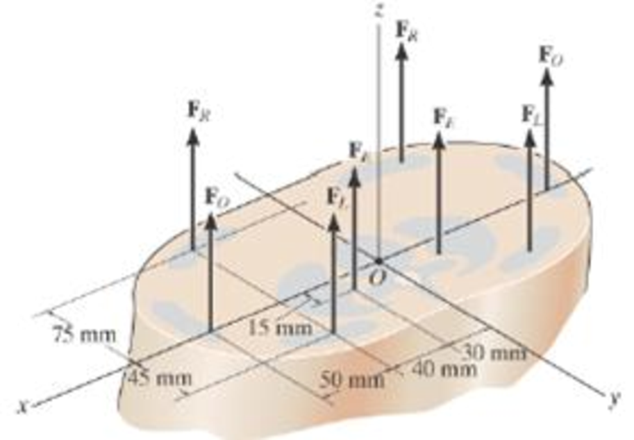
A biomechanical model of the lumbar region of the human trunk is shown. The forces acting in the four muscle groups consist of FR = 35 N for the rectus. FO = 45 N for the oblique. FL = 23 N for the lumbar latissimus dorsi, and FE = 32 N for the erector spinae. These loadings are symmetric with respect to the y-z plane. Replace this system of parallel forces by an equivalent force and couple moment acting at the spine, point O. Express the results in Cartesian
Want to see the full answer?
Check out a sample textbook solution
Chapter 4 Solutions
Engineering Mechanics: Statics Plus Modified Mastering Engineering Revision With Pearson Etext -- Access Card Package (14th Edition)
Additional Engineering Textbook Solutions
Statics and Mechanics of Materials (5th Edition)
Automotive Technology: Principles, Diagnosis, and Service (5th Edition)
Engineering Mechanics: Dynamics (14th Edition)
Thinking Like an Engineer: An Active Learning Approach (4th Edition)
Mechanics of Materials
Applied Fluid Mechanics (7th Edition)


- SITUATION 5: The hook shown in the Fig. SRB-004 is subjected to three forces A, B, and C. If A = 8 kN, B = 5 kN and angle α = 32°. Calculate the value of angle θ (degrees) if the resultant of the three forces is 7.5 kN along the y-axis. (Answer: 37.32) If the resultant of the three forces A, B, and C is 14.5 kN, and θ = 83°, what is the value of C, in kN? (Answer: 6.64) If C = 6 kN, and θ = 45°, how much is the resultant pulling force in the eyebolt, in kN? (Answer: 9.49)arrow_forwardThe system shown consists of 3 cables. For instance; cable C12 joins points 1 and 2. The coordinates of point 1 are (7.79, 0, 0) m, those of point 2 are (0, 7.58, 9.77) m, and those of point 3 are (0, 7.58, -9.77) m. The force P = 99 kN. Determine the force in cable C14.arrow_forwardThe hydraulic cylinder shown in the figure exerts a force of 3 kN directed to the right at point B and to the left at point E. Determine the magnitude of the couple M required to rotate the drum at constant speed clockwise. The picture is attachedarrow_forward
- The wheels, axle, and handles of a wheelbarrow weigh W = 55 N. The load chamber and its contents weigh WL = 623 N. The drawing shows these two forces in two different wheelbarrow designs. To support the wheelbarrow in equilibrium, the man’s hands apply a force to the handles that is directed vertically upward. Consider a rotational axis at the point where the tire contacts the ground, directed perpendicular to the plane of the paper. Find the magnitude of the man’s force for both designs.arrow_forwardThe system shown consists of 3 cables. For example; cable C12 joins points 1 and 2. The coordinates of point 1 are ( 2.44, 0, 0 ) m, those of point 2 are ( 0, 2.09, -4.34 ) m, and those of point 3 are ( 0, 2.09 , 4.34 ) meter. The force P = 37 kN. Determine the force in cable C14.arrow_forwardThe 1800lbin. couple is applied to member DEF of the pin-connected frame. Find the internal force systems acting on sections 1 and 2.arrow_forward
- The figure shows a wire cutter. Determine the cutting force on the wire at A when the 75-N forces are applied to the handgrips. (Hint: The horizontal components of pin forces at B and D are zero due to symmetry.)arrow_forwardFind the internal force system acting on section 3 for the pin-connected frame.arrow_forwardThe light boom AB is attached to a vertical wall by a ball and socket joint at A and supported by two cables at B. A force P is applied at B where P = 16i - 13j kN.Note that the reaction force at A acts along the boom because it is a two-force member. Calculate the magnitude of the reaction force at A in kN. Determine the magnitude of the moment of P about the y-axis in Nm. Determine the magnitude of the moment of P about the z-axis in Nm. Determine the magnitude of the moment of P about the origin (point O) in Nm.arrow_forward
- There are two masses that are attached to a uniform meter stick. The masses of m1 and m2 are as given and the meter stick weighs 150 grams. A force F with unknown magnitude is applied on one end of the stick at an angle of 30 degrees to balance the system. a.) What is the magnitude of F? b.) What are the reaction forces on the support?arrow_forwardFor the spring assemblage shown below, determine the displacement at node 2 and the forces in each spring element. Also determine the force F3. Given: Node 3 displaces an amount 8 = 12.5 mm in the positive x direction because of the force F3 and k1 k2 175 kN/m.arrow_forwardThe forces acting on the arm of an athlete doing shoulder exercises are shown in the figure. The athlete holds his arm at an angle of β = 30° with the horizontal axis . Point O represents the axis of rotation in the shoulder joint, point A represents the connection point of the deltoid muscle to the humerus, point B represents the center of gravity of the arm, and point C represents the application point of the force acting on the hand. The distances between the rotation axis (O point) of the shoulder joint and the points A, B and C are a=22 cm , b =33 cm and c= 60 cm , respectively . A force of F= 120 N, which makes an angle of γ=30° with the vertical from the point C, acts on the athlete's hand . Weight of the athlete's armW= 80 N. The direction of application of the Fm muscle force makes an angle of α=20° with the longitudinal axis of the arm. According to this; a) Calculate the muscle strength F M b) Calculate the angle θ of the joint reaction force F J with the horizontal.…arrow_forward
 International Edition---engineering Mechanics: St...Mechanical EngineeringISBN:9781305501607Author:Andrew Pytel And Jaan KiusalaasPublisher:CENGAGE L