
Fundamentals of Applied Electromagnetics (7th Edition)
7th Edition
ISBN: 9780133356816
Author: Fawwaz T. Ulaby, Umberto Ravaioli
Publisher: PEARSON
expand_more
expand_more
format_list_bulleted
Concept explainers
Videos
Textbook Question
Chapter 5, Problem 19P
Three long, parallel wires are arranged as shown in Fig. P5.19. Determine the force per unit length acting on the wire carrying I3.
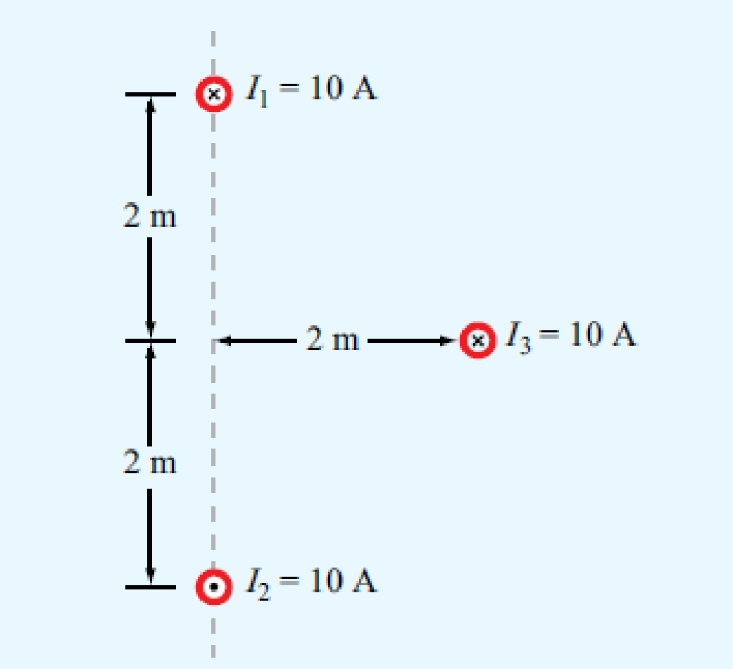
Figure P5.19 Three parallel wires of Problem 5.19.
Expert Solution & Answer
Want to see the full answer?
Check out a sample textbook solution
Students have asked these similar questions
Solve the linear system described by a space model below:
a)We have a two-wire overhead transmission line, powered by a constant voltage source of 700 V. The values for the inductance of the conductors are 2.348x10⁻³ H/km and the capacitance values are 6.325x10⁻⁹ F/km. Assuming an ideal (no loss) line and its length at 130 km, determine the natural impedance of the line.
b) What is the transient phenomenon in a transmission line? As an example of its causes.
A plastic ball with a mass of 2 grams is hung on a 10 cm long thin rope as in the spherical figure,a uniform electric field is applied in the + x direction. When the rope is made at an angle of 15 ° verticallyIf the ball is in equilibrium, calculate the net load (in uC) on the plastic ball.
Chapter 5 Solutions
Fundamentals of Applied Electromagnetics (7th Edition)
Ch. 5.1 - What are the major differences between the...Ch. 5.1 - Prob. 2CQCh. 5.1 - How is the direction of the magnetic moment of a...Ch. 5.1 - If one of two wires of equal length is formed into...Ch. 5.1 - An electron moving in the positive x direction...Ch. 5.1 - A proton moving with a speed of 2 106 m/s through...Ch. 5.1 - A charged particle with velocity u is moving in a...Ch. 5.1 - A horizontal wire with a mass per unit length of...Ch. 5.1 - A square coil of 100 turns and 0.5 m long sides is...Ch. 5.2 - Two infinitely long parallel wires carry currents...
Ch. 5.2 - Devise a right-hand rule for the direction of the...Ch. 5.2 - What is a magnetic dipole? Describe its magnetic...Ch. 5.2 - Prob. 6ECh. 5.2 - A wire carrying a current of 4 A is formed into a...Ch. 5.2 - Prob. 8ECh. 5.3 - What are the fundamental differences between...Ch. 5.3 - Prob. 9CQCh. 5.3 - Compare the utility of applying the BiotSavart law...Ch. 5.3 - Prob. 11CQCh. 5.3 - A current I flows in the inner conductor of a long...Ch. 5.3 - The metal niobium becomes a superconductor with...Ch. 5.5 - What are the three types of magnetic materials and...Ch. 5.5 - What causes magnetic hysteresis in ferromagnetic...Ch. 5.5 - Prob. 14CQCh. 5.5 - The magnetic vector M is the vector sum of the...Ch. 5.6 - With reference to Fig. 5-24, determine the single...Ch. 5.7 - Prob. 15CQCh. 5.7 - What is the difference between self-inductance and...Ch. 5.7 - Prob. 17CQCh. 5.7 - Use Eq. (5.89) to obtain an expression for B at a...Ch. 5 - An electron with a speed of 8 106 m/s is...Ch. 5 - When a particle with charge q and mass m is...Ch. 5 - The circuit shown in Fig. P5.3 uses two identical...Ch. 5 - The rectangular loop shown in Fig. P5.4 consists...Ch. 5 - In a cylindrical coordinate system, a 2 m long...Ch. 5 - Prob. 6PCh. 5 - Prob. 7PCh. 5 - Prob. 8PCh. 5 - The loop shown in Fig. P5.9 consists of radial...Ch. 5 - An infinitely long, thin conducting sheet defined...Ch. 5 - An infinitely long wire carrying a 25 A current in...Ch. 5 - Prob. 12PCh. 5 - Prob. 13PCh. 5 - Prob. 14PCh. 5 - A circular loop of radius a carrying current I1 is...Ch. 5 - Prob. 16PCh. 5 - Prob. 17PCh. 5 - Prob. 18PCh. 5 - Three long, parallel wires are arranged as shown...Ch. 5 - A square loop placed as shown in Fig. P5.20 has 2...Ch. 5 - Prob. 21PCh. 5 - Prob. 22PCh. 5 - Repeat Problem 5.22 for a current density J=zJ0er.Ch. 5 - In a certain conducting region, the magnetic field...Ch. 5 - Prob. 25PCh. 5 - Prob. 26PCh. 5 - Prob. 27PCh. 5 - A uniform current density given by J=zj0 (A/m2)...Ch. 5 - A thin current element extending between z = L/2...Ch. 5 - In the model of the hydrogen atom proposed by Bohr...Ch. 5 - Iron contains 8.5 1028 atoms/m3. At saturation,...Ch. 5 - The xy plane separates two magnetic media with...Ch. 5 - Given that a current sheet with surface current...Ch. 5 - In Fig. P5.34, the plane defined by x y = 1...Ch. 5 - The plane boundary defined by z = 0 separates air...Ch. 5 - Prob. 36PCh. 5 - Prob. 37PCh. 5 - A solenoid with a length of 20 cm and a radius of...Ch. 5 - Prob. 39PCh. 5 - The rectangular loop shown in Fig. P5.40 is...Ch. 5 - Determine the mutual inductance between the...
Knowledge Booster


Learn more about
Need a deep-dive on the concept behind this application? Look no further. Learn more about this topic, electrical-engineering and related others by exploring similar questions and additional content below.Similar questions
- Given a field of H=3xyax+5yxzay , Find its curl at P(2,3,1)arrow_forwardAn Underground cable of length 40 Km has a conductor of diameter of 1.5 cm and a sheath of inner diameter 5 cm. If the permittivity of insulation is 3.5, Analyze the following Electrical Parameters of the UG-cables (i) the inductance per km length (ii) capacitance per km length. (iii) Natural impedance (Surge Impedance) and (iv) velocity of propagation of the travelling waves.arrow_forwardA cylindrical capacitor is made of two concentric conducting cylinders. The inner cylinder has radius R1 = 19 cm and carries a uniform charge per unit length of λ = 30 μC/m. The outer cylinder has radius R2 = 25 cm and carries an equal but opposite charge distribution as the inner cylinder. a. Use Gauss’ Law to write an equation for the electric field at a distance R1 < r < R2 from the center of the cylinders. Write your answer in terms of λ, r, and e0. E= b. Write an equation for the energy density due to the electric field between the cylinders in terms of λ, r, and e0. u = c. Consider a thin cylindrical shell of thickness dr and radius R1 < r < R2 that is concentric with the cylindrical capacitor. Write an equation for the total energy per unit length contained in the shell in terms of λ, r, dr, and ε0. dU/l = d. Calculate the energy stored per unit length in the capacitor in units of joules per meter. U/l = e. Calculate the electric potential difference between…arrow_forward
- The relative dielectric coefficient of the planar electrode system given in the figure is Er = Er0 - n. It changes linearly according to the x relation. Er0 = 7.2 for this electrode system; n = 1.8 cm ^ -1 and the gap between electrodes is given as a = 3 cm. 26 kV direct voltage is applied to this planar electrode system, so find the amplitude of the electric field strength at point A (2.7cm, 3cm). (Edge effects will be neglected, electrode length b <15 cm) y 4 a (cm) -> electrode electrodearrow_forwardA parallel plate capacitor of width W, length L, and separation d has a solid dielectric slab of permittivity ?(?) as shown in the figure. A potential difference ?? Volts is applied to the capacitor terminals. Neglecting fringing, fori. ?(?) = ?0ii. ?(?) = ?0??Determine;a) The electric field intensity ?⃗ ,b) The displacement vector ?⃗ ,c) The capacitance ?,d) The stored electrostatic energy ??e) Magnitude and the direction of the force acting on the slab ??⃗⃗⃗⃗arrow_forwardA resistor (5 Ω) and capacitor (0.05 F) are joined in series with an electromotive force E(t) = 30 −t V. If there is nocharge on the capacitor at time t = 0, find the ensuing charge on the capacitor at time t. The following lineardifferential equation models the charge on the capacitor, q(t). (check the image) How do I go about solving this?arrow_forward
- pls answer in 30 mins sir subject (control engineering) pls use this matrix num sir (AD 200153)arrow_forwardEstimate the AEP for a 3-MW wind turbine in a wind regime that has a CF= 30%. For this turbine explain why the increase of wind speed to levels greater than 25 m/s generates less electrical power compared to wind speeds around 11 m/sarrow_forwardConsider a line of charge that extends along the x axis from x = 0 to x = 4.7 m. The line has a non-uniform linear charge density given by ?λ(x) = 8.4 x2 (nC/m). Calculate the electric potential at x = -1.3 m. Use k = 9 x 10⁹ N m2 / C2. You may need to use u-substitution if you choose to evaluate the integral yourself. (Please answer to the fourth decimal place - i.e 14.3225)arrow_forward
- The surface charge density p = 3R C / m² is grounded on the surface of the inside of the two concentric thin conductive spheres given in the figure. The space between the two spheres is filled with a dielectric of & 5a. Find a) the electric field intensity between the spheres,b) the potential difference between the spheres, andc) the capacitance between the spheres, and the outer sphere surface is present.Constants: at photoarrow_forwardA lossy capacitor Cx, rated for operation of 5 kV, 50 Hz is represented by an equivalent circuit with an ideal capacitor Cp in parallel with a resistor Rp. Cp is 0.102 microF and Rp=1.25 Mohm. The power loss, and loss tangent of this lossy capacitor at rated voltage respectively ?arrow_forwardPicture attached of question The 1D Poisson equation for the calculation of electrostatic potential can be written as: ?2?(?) ??2 = − ? ?(?) ???0 where q is the change of electron, N is the total charge density, and ε is material permittivity which consists of the relative permittivity εr and the permittivity of a vacuum ε0. Solve the above equation and find the potential for a p-n junction assuming the depletion approximation, i.e., when a concentration of acceptors NA is much larger than a concentration of donors ND so that: ?? ≫ ?? and this lead to ?? ≫ ??.arrow_forward
arrow_back_ios
SEE MORE QUESTIONS
arrow_forward_ios
Recommended textbooks for you
 Introductory Circuit Analysis (13th Edition)Electrical EngineeringISBN:9780133923605Author:Robert L. BoylestadPublisher:PEARSON
 Delmar's Standard Textbook Of ElectricityElectrical EngineeringISBN:9781337900348Author:Stephen L. HermanPublisher:Cengage Learning
 Programmable Logic ControllersElectrical EngineeringISBN:9780073373843Author:Frank D. PetruzellaPublisher:McGraw-Hill Education
 Fundamentals of Electric CircuitsElectrical EngineeringISBN:9780078028229Author:Charles K Alexander, Matthew SadikuPublisher:McGraw-Hill Education
 Electric Circuits. (11th Edition)Electrical EngineeringISBN:9780134746968Author:James W. Nilsson, Susan RiedelPublisher:PEARSON
 Engineering ElectromagneticsElectrical EngineeringISBN:9780078028151Author:Hayt, William H. (william Hart), Jr, BUCK, John A.Publisher:Mcgraw-hill Education,
Introductory Circuit Analysis (13th Edition)
Electrical Engineering
ISBN:9780133923605
Author:Robert L. Boylestad
Publisher:PEARSON
Delmar's Standard Textbook Of Electricity
Electrical Engineering
ISBN:9781337900348
Author:Stephen L. Herman
Publisher:Cengage Learning
Programmable Logic Controllers
Electrical Engineering
ISBN:9780073373843
Author:Frank D. Petruzella
Publisher:McGraw-Hill Education
Fundamentals of Electric Circuits
Electrical Engineering
ISBN:9780078028229
Author:Charles K Alexander, Matthew Sadiku
Publisher:McGraw-Hill Education
Electric Circuits. (11th Edition)
Electrical Engineering
ISBN:9780134746968
Author:James W. Nilsson, Susan Riedel
Publisher:PEARSON
Engineering Electromagnetics
Electrical Engineering
ISBN:9780078028151
Author:Hayt, William H. (william Hart), Jr, BUCK, John A.
Publisher:Mcgraw-hill Education,
Demos: Dielectric breakdown; Author: Caltech's Feynman Lecture Hall;https://www.youtube.com/watch?v=2YrHh1ikefI;License: Standard Youtube License