
Concept explainers
Videos
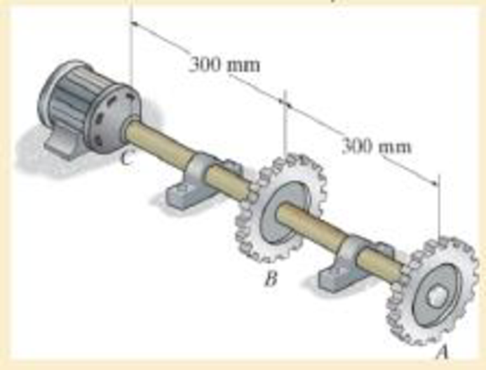
The shaft is made of A992 steel and has an allowable shear stress of τallow = 75 MPa. When the shaft is rotating at 300 rpm, the motor supplies 8 kW of power, while gears A and B withdraw 5 kW and 3 kW, respectively. Determine the required minimum diameter of the shaft to the nearest millimeter. Also, find the rotation of gear A relative to C.
The required minimum diameter of the shaft.
The angle of twist of gear A relative to gear C.
Answer to Problem 1RP
The required minimum diameter of the shaft is
The angle of twist of gear A relative to gear C is
Explanation of Solution
Given information:
The allowable shear stress in the shaft is 75 MPa.
The motor supplies power of 8 kW.
Gear A and B withdraws power of 5 kW and 3 kW.
Shaft rotates at 300 rpm.
Calculation:
The expression for the power transmitted
Here, T is the applied torque and
Rearrange Equation (1) to find the torque at A.
Here,
The expression for angular velocity of the shaft
Here, f is the frequency of shaft’s rotation.
Substitute
Substitute 5 kW for
Find the torque at C.
Here,
Substitute 8 kW for
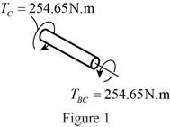
Sketch the internal torque in the segment BC of the shaft as shown in Figure 1.
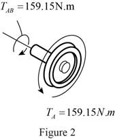
Sketch the internal torque in the segment AB of the shaft as shown in Figure 2.
Refer Figure 1 and Figure 2.
Segment BC of the shat is subjected to a greater internal torque of
The torsion formula for allowable maximum shear stress in the solid shaft
Here,
The outer radius of the shaft is r.
The polar moment of inertia for a solid shaft of radius
Substitute r for c and
Substitute 75 MPa for
The diameter of the shaft is twice the radius of the shaft. So the value of diameter is 26 mm.
Therefore, the required minimum diameter of the shaft is
Determine the angle of twist
Here, L is the length of the shaft and G is the shear modulus of elasticity of the material.
Rearrange Equation (7) for angle of twist of gear A relative to gear C
Refer the properties of A992 steel.
The value of shear modulus of elasticity of A992 steel is 75 GPa.
The value of radius of the solid shaft is 13 mm.
Substitute
Refer Figure 2.
The torque in the region AB of the shaft is
Refer Figure 1.
The torque in the region BC of the shaft is
Substitute
Therefore, the angle of twist of gear A relative to gear C is
Want to see more full solutions like this?
Chapter 5 Solutions
Mechanics of Materials


- The A-36 steel tubular shaft is 2 m long and has an outer diameter of 50 mm. When it is rotating at 40 rad>s, it transmits 25 kW of power from the motor M to the pump P. Determine the smallest thickness of the tube if the allowable shear stress is tallow = 80 MPa.arrow_forwardThe A-36 solid steel shaft is 2 m long and has a diameter of 60 mm. It is required to transmit 60 kW of power from the motor M to the pump P. Determine the smallest angular velocity the shaft if the allowable shearstress is tallow = 80 MPa.arrow_forwardThe solid steel shaft AC has a diameter of 25 mm and is supported by smooth bearings at D and E. It is coupled to a motor at C, which delivers 3 kW of power to the shaft while it is turning at 50 rev>s. If gears A and B remove1 kW and 2 kW, respectively, determine the maximum shear stress in the shaft within regions AB and BC. The shaft is free to turn in its support bearings D and E.arrow_forward
- The shaft below is made of A992 steel and has an allowable shear stress of tadm = 75 MPa. When the shaft is rotating at 300 rpm, the motor provides 8 kW of power, while gears A and B draw 5 kW and 3 kW, respectively. Determine the minimum diameter required for shaft. Also, find the angle of twist of the gear A with respect to C.arrow_forwardThe gear motor can develop 3 hp when it turns at 150 rev>min. If the allowable shear stress for the shaft is tallow = 12 ksi, determine the smallest diameter of the shaft to the nearest 1 8 in. that can be used.arrow_forwardThe solid steel shaft DF has a diameter of 25 mm and is supported by smooth bearings at D and E. It is coupled to a motor at F, which delivers 12 kW of power to the shaft while it is turning at 50 rev>s. If gears A, B, and C remove3 kW, 4 kW, and 5 kW respectively, determine the maximum shear stress in the shaft within regions CF and BC. The shaft is free to turn in its support bearings D and E.arrow_forward
- The solid steel shaft carries the torques Tl = 750 N • m and T2 = 1200 N • m.using Ll = 1.0 = 2.5 m and G = 83 GPa, determine the smallest allowable diameter of the shaft if the shear stress is limited to 60 MPa and the angle of rotation of the free end is not to exceed 40arrow_forwardThe steel shaft is made from two segments: AC has a diameter of 0.5 in., and CB has a diameter of 1 in. If the shaft is fixed at its ends A and B and subjected to a torque of 500 lb.ft at point C, determine the maximum shear stress in the shaft. G = 10.8x10^3 ksiarrow_forwardThe drive shaft of the motor is made of a material having an allowable shear stress of τallow= 72 MPa. the shaft is operating at an angular velocity of 1700 rev/min. Take ci= 0.75 co. A) If the motor is to deliver a power of 25 kW, determine the required minimum outer diameter of the tubular shaft to the nearest mm. B)Determine the required corresponding inner diameter of the tubular shaft to the nearest mm.arrow_forward
- The gear motor can develop 14 hp when it turns at 600 rev>min. If the shaft has a diameter of 12 in., determine the maximum shear stress in the shaft.arrow_forwardA shaft has three segments. AB and CD are made from C86100 bronze and BC is made from 2014-T6 aluminum. The rod is fixed at its ends and is subjected to the torque of T = 750 lb⋅⋅ft. If the bronze segments have a diameter of 1.5 inch, and the diameter of the aluminum segment is 0.7 inch, determine the maximum shear stress in the shaft (in ksi).arrow_forwardThe shaft is subjected to a distributed torque along its length of t = (10x2) N # m>m, where x is in meters. If the maximum stress in the shaft is to remain constant at 80 MPa, determine the required variation of the radius c of the shaft for 0 ≤ x ≤ 3 m.arrow_forward
 Elements Of ElectromagneticsMechanical EngineeringISBN:9780190698614Author:Sadiku, Matthew N. O.Publisher:Oxford University Press
 Mechanics of Materials (10th Edition)Mechanical EngineeringISBN:9780134319650Author:Russell C. HibbelerPublisher:PEARSON
 Thermodynamics: An Engineering ApproachMechanical EngineeringISBN:9781259822674Author:Yunus A. Cengel Dr., Michael A. BolesPublisher:McGraw-Hill Education
 Control Systems EngineeringMechanical EngineeringISBN:9781118170519Author:Norman S. NisePublisher:WILEY
 Mechanics of Materials (MindTap Course List)Mechanical EngineeringISBN:9781337093347Author:Barry J. Goodno, James M. GerePublisher:Cengage Learning
 Engineering Mechanics: StaticsMechanical EngineeringISBN:9781118807330Author:James L. Meriam, L. G. Kraige, J. N. BoltonPublisher:WILEY