
EBK INTRODUCTORY CIRCUIT ANALYSIS
13th Edition
ISBN: 9780100668232
Author: Boylestad
Publisher: YUZU
expand_more
expand_more
format_list_bulleted
Concept explainers
Videos
Textbook Question
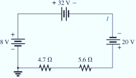
Chapter 5, Problem 22P
Determine the current I and its direction for each network in Fig. 5.109. Before solving for I, redraw each network with a single voltage source.
Expert Solution & Answer
Want to see the full answer?
Check out a sample textbook solution
Students have asked these similar questions
For each configuration in Fig. 5.85, find the individual (not combinations of) elements (voltages sources and/or resistors) that are in series. If necessary, use the fact that elements in series have the same current. Simply list those that satisfy the conditions for a series relationship.
EX:- re drow the network of fig. 5.183 for the AC respon with the re model inserted between the appropriate terminals include ro.
For the series configuration in Fig . 5.98 constructed using standard value resistor
without making a single calculation, which resistive element will have the most voltage across it? Which will have the least? which resistor will have the most impact on the total resistance and the the resulting current ? Find the total resistance and the current.
Find the voltage across each element and review your response to part (a)
Chapter 5 Solutions
EBK INTRODUCTORY CIRCUIT ANALYSIS
Ch. 5 - For each configuration in Fig. 5.88, find the...Ch. 5 - For each configuration in Fig. 5.89, find the...Ch. 5 - Find the total resistance RT for each...Ch. 5 - Find the total resistance RT for each...Ch. 5 - For each circuit board in Fig. 5.92, �nd the...Ch. 5 - For the circuit in Fig. 5.93, composed of standard...Ch. 5 - For each configuration in Fig. 5.94, determine the...Ch. 5 - Find the resistance R, given the ohmmeter reading...Ch. 5 - What is the ohmmeter reading for each...Ch. 5 - For the series configuration in Fig. 5.97,...
Ch. 5 - For the series configuration in Fig. 5.98,...Ch. 5 - Find the applied voltage necessary to develop the...Ch. 5 - For each network in Fig. 5.100, constructed of...Ch. 5 - For each configuration in Fig. 5.101, what are the...Ch. 5 - For each configuration of Fig. 5.102, find the...Ch. 5 - For the circuit in Fig. 5.103, constructed of...Ch. 5 - Find the unknown quantities for the circuit of...Ch. 5 - Find the unknown quantities for the circuit in...Ch. 5 - Eight holiday lights are connected in series as...Ch. 5 - For the conditions specified in Fig. 5.107,...Ch. 5 - Combine the series voltage sources in Fig. 5.108,...Ch. 5 - Determine the current I and its direction for each...Ch. 5 - Find {he unknown voltage source and resistor for...Ch. 5 - Using Kirchhoffs voltage law, find the unknown...Ch. 5 - Find the current I for the network of Fig. 5.112....Ch. 5 - Using Kirchhoffs voltage law, determine the...Ch. 5 - Using Kirchhoffs voltage law, find the unknown...Ch. 5 - Determine the values of the unknown resistors in...Ch. 5 - For the configuration in Fig. 5.116, with standard...Ch. 5 - Using the voltage divider rule, find the indicated...Ch. 5 - Using the voltage divider rule or Kirchhoffs...Ch. 5 - Using the voltage divider rule or Kirchhoffs...Ch. 5 - Using the information provided, find the unknown...Ch. 5 - Using the voltage divider rule, �nd the unknown...Ch. 5 - Design a voltage divider circuit that will permit...Ch. 5 - Design the voltage divider in Fig. 5.122 such that...Ch. 5 - Find the voltage across each resistor in Fig....Ch. 5 - Design the circuit in Fig. 5.124 such that...Ch. 5 - Determine the voltages Va,Vb, and Vab for the...Ch. 5 - Determine the current I (with direction) and the...Ch. 5 - For the network in Fig. 5.127 determine the...Ch. 5 - Given the information appearing in Fig. 5.128,...Ch. 5 - Determine the values of R1,R2,R3, and R4 for the...Ch. 5 - For the network in Fig. 5.130, determine the...Ch. 5 - For the integrated circuit in Fig. 5.131,...Ch. 5 - For the integrated circuit in Fig. 5.132,...Ch. 5 - Find the internal resistance of a battery that has...Ch. 5 - Find the voltage to the load (full-and conditions)...Ch. 5 - Determine the current through the circuit in Fig....Ch. 5 - Use the computer to verify the results of Example...Ch. 5 - Use the computer to verify the results of Example...Ch. 5 - Use the computer to verify the results of Example...
Additional Engineering Textbook Solutions
Find more solutions based on key concepts
Assume a telephone signal travels through a cable at two-thirds the speed of light. How long does it take the s...
Electric Circuits (10th Edition)
Three point charges of equal magnitude q, that will yield a zero net electric field at the origin.
Engineering Electromagnetics
With respect to the circuit in Fig. 5.90, (a) employ Thévenin’s theorem to determine the equivalent network see...
Loose Leaf for Engineering Circuit Analysis Format: Loose-leaf
When travelers from the USA and Canada visit Europe, they encounter a different power distribution system. Wall...
Electric machinery fundamentals
A constant voltage of 10V is applied to a 50H inductance, as shown in Figure P3.51 Figure P3 51 The current in ...
Electrical Engineering: Principles & Applications (7th Edition)
Analog Voltmeter Design Figure P2-98(a) shows a voltmeter circuit consisting of a D'Arsonval meter, two series ...
ANALYSIS+DESIGN OF LINEAR CIRCUITS(LL)
Knowledge Booster


Learn more about
Need a deep-dive on the concept behind this application? Look no further. Learn more about this topic, electrical-engineering and related others by exploring similar questions and additional content below.Similar questions
- For the network of Fig. 5.152 , determine V CC for a voltage gain of Av = -160.arrow_forwardUsing the voltage divider rule or Kirchhoff's voltage law, determine the unknown voltage for the configuration in Fig. 5.118. Do not calculate the current!arrow_forwardReplace the network in Fig. 5.104 with an equivalent three-resistor network.arrow_forward
- For the circuit in Fig. 5.88, composed of standard values: a. Which resistor will have the most impact on the total resistance? b. On an approximate basis, which resistors can be ignored when determining the total resistance? c. Find the total resistance, and comment on your results for parts (a) and (b).arrow_forwardFor the configuration in fig . 5.116, with standard resistor values : by inspection , which resistor will receive the largest share of the applied voltage ? Why? how much larger will voltage V3 be compared to V2 and V1 Find the voltage across the largest resistor using the the voltage divider rule Find the voltage across the series combination of resistors R2 and R3arrow_forwardFind Io in Fig. 5 using mesh analysis.arrow_forward
- Metal interconnect lines in Ie circuits form parasitic MOS capacitors as illustrated in Fig. 5-37. Generally. one wants to prevent the underlying Si substrate from becoming inverted. Otherwise, parasitic transistors may be formed and create undesirable current paths between the N+ diffusions.arrow_forward5.32 Calculate ix and vo in the circuit of Fig. 5.70. Find thepower dissipated by the 60-kΩ resistor.arrow_forward5. I need help with this practice problemarrow_forward
- 12/ A junction in a circuit where two or more circuit elements are connected together is known as Node. Select one: True Falsearrow_forwardDetermine the total resistance RsubT, using equivalent three terminal networks.arrow_forwardDesign a charger circuit for mobile phone from:220V, 50Hz AC sourceSelect the proper circuit topologies and components. (please explain in detail)arrow_forward
arrow_back_ios
SEE MORE QUESTIONS
arrow_forward_ios
Recommended textbooks for you
 Delmar's Standard Textbook Of ElectricityElectrical EngineeringISBN:9781337900348Author:Stephen L. HermanPublisher:Cengage Learning
Delmar's Standard Textbook Of Electricity
Electrical Engineering
ISBN:9781337900348
Author:Stephen L. Herman
Publisher:Cengage Learning
Kirchhoff's Rules of Electrical Circuits; Author: Flipping Physics;https://www.youtube.com/watch?v=d0O-KUKP4nM;License: Standard YouTube License, CC-BY