
EBK INTRODUCTORY CIRCUIT ANALYSIS
13th Edition
ISBN: 9780133923872
Author: Boylestad
Publisher: PEARSON CUSTOM PUB.(CONSIGNMENT)
expand_more
expand_more
format_list_bulleted
Concept explainers
Videos
Textbook Question
thumb_up100%
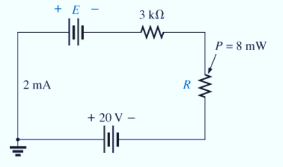
Chapter 5, Problem 23P
Find {he unknown voltage source and resistor for the networks in Fig. 5.110. First combine the series voltage sources into a single source. Indicate the direction of the resulting current.
Expert Solution & Answer

Learn your wayIncludes step-by-step video

schedule08:39
Students have asked these similar questions
EX:- re drow the network of fig. 5.183 for the AC respon with the re model inserted between the appropriate terminals include ro.
For each configuration in Fig. 5.85, find the individual (not combinations of) elements (voltages sources and/or resistors) that are in series. If necessary, use the fact that elements in series have the same current. Simply list those that satisfy the conditions for a series relationship.
For the series configuration in Fig . 5.98 constructed using standard value resistor
without making a single calculation, which resistive element will have the most voltage across it? Which will have the least? which resistor will have the most impact on the total resistance and the the resulting current ? Find the total resistance and the current.
Find the voltage across each element and review your response to part (a)
Chapter 5 Solutions
EBK INTRODUCTORY CIRCUIT ANALYSIS
Ch. 5 - For each configuration in Fig. 5.88, find the...Ch. 5 - For each configuration in Fig. 5.89, find the...Ch. 5 - Find the total resistance RT for each...Ch. 5 - Find the total resistance RT for each...Ch. 5 - For each circuit board in Fig. 5.92, �nd the...Ch. 5 - For the circuit in Fig. 5.93, composed of standard...Ch. 5 - For each configuration in Fig. 5.94, determine the...Ch. 5 - Find the resistance R, given the ohmmeter reading...Ch. 5 - What is the ohmmeter reading for each...Ch. 5 - For the series configuration in Fig. 5.97,...
Ch. 5 - For the series configuration in Fig. 5.98,...Ch. 5 - Find the applied voltage necessary to develop the...Ch. 5 - For each network in Fig. 5.100, constructed of...Ch. 5 - For each configuration in Fig. 5.101, what are the...Ch. 5 - For each configuration of Fig. 5.102, find the...Ch. 5 - For the circuit in Fig. 5.103, constructed of...Ch. 5 - Find the unknown quantities for the circuit of...Ch. 5 - Find the unknown quantities for the circuit in...Ch. 5 - Eight holiday lights are connected in series as...Ch. 5 - For the conditions specified in Fig. 5.107,...Ch. 5 - Combine the series voltage sources in Fig. 5.108,...Ch. 5 - Determine the current I and its direction for each...Ch. 5 - Find {he unknown voltage source and resistor for...Ch. 5 - Using Kirchhoffs voltage law, find the unknown...Ch. 5 - Find the current I for the network of Fig. 5.112....Ch. 5 - Using Kirchhoffs voltage law, determine the...Ch. 5 - Using Kirchhoffs voltage law, find the unknown...Ch. 5 - Determine the values of the unknown resistors in...Ch. 5 - For the configuration in Fig. 5.116, with standard...Ch. 5 - Using the voltage divider rule, find the indicated...Ch. 5 - Using the voltage divider rule or Kirchhoffs...Ch. 5 - Using the voltage divider rule or Kirchhoffs...Ch. 5 - Using the information provided, find the unknown...Ch. 5 - Using the voltage divider rule, �nd the unknown...Ch. 5 - Design a voltage divider circuit that will permit...Ch. 5 - Design the voltage divider in Fig. 5.122 such that...Ch. 5 - Find the voltage across each resistor in Fig....Ch. 5 - Design the circuit in Fig. 5.124 such that...Ch. 5 - Determine the voltages Va,Vb, and Vab for the...Ch. 5 - Determine the current I (with direction) and the...Ch. 5 - For the network in Fig. 5.127 determine the...Ch. 5 - Given the information appearing in Fig. 5.128,...Ch. 5 - Determine the values of R1,R2,R3, and R4 for the...Ch. 5 - For the network in Fig. 5.130, determine the...Ch. 5 - For the integrated circuit in Fig. 5.131,...Ch. 5 - For the integrated circuit in Fig. 5.132,...Ch. 5 - Find the internal resistance of a battery that has...Ch. 5 - Find the voltage to the load (full-and conditions)...Ch. 5 - Determine the current through the circuit in Fig....Ch. 5 - Use the computer to verify the results of Example...Ch. 5 - Use the computer to verify the results of Example...Ch. 5 - Use the computer to verify the results of Example...
Additional Engineering Textbook Solutions
Find more solutions based on key concepts
The switch in the bottom loop of Fig. P6.1 is closed at t = 0 and then opened at a later time t1. What is the d...
Fundamentals of Applied Electromagnetics (7th Edition)
Broadly speaking, what are the two main objectives of electrical systems?
Electrical Engineering: Principles & Applications (7th Edition)
Determine the reactions at the supports A and B. El is constant.
Mechanics of Materials (10th Edition)
What is a property?
Starting Out With Visual Basic (7th Edition)
The ____________ is always transparent.
Web Development and Design Foundations with HTML5 (9th Edition) (What's New in Computer Science)
It is a common practice in object-oriented programming to make all of a classs fields public.
Starting Out with Programming Logic and Design (5th Edition) (What's New in Computer Science)
Knowledge Booster


Learn more about
Need a deep-dive on the concept behind this application? Look no further. Learn more about this topic, electrical-engineering and related others by exploring similar questions and additional content below.Similar questions
- For each configuration in fig.5.94 determine the ohmmeter readingarrow_forwardFor the circuit in Fig. 5.88, composed of standard values: a. Which resistor will have the most impact on the total resistance? b. On an approximate basis, which resistors can be ignored when determining the total resistance? c. Find the total resistance, and comment on your results for parts (a) and (b).arrow_forward5. I need help with this practice problemarrow_forward
- Refer to the transistorized circuit. Keep in mind that although you do not know the current-voltage relationship of the device, it still complies with the LCK and the LVK. (a) If Id = 1.5 mA, calculate Vds. (b) If Id = 2 mA and Vg = 3 V, calculate Vgs.arrow_forwardFind Io in Fig. 5 using mesh analysis.arrow_forward5.32 Calculate ix and vo in the circuit of Fig. 5.70. Find thepower dissipated by the 60-kΩ resistor.arrow_forward
- Given the power dissipated in each resistor in Fig. 5.8 as follows: P1= P5= 4.5W, P2 = 5W, P3= 1.332W,P4 = 2.668W . The total supply voltage is 12v, determine the resistances, R1 to R5.arrow_forwardFor the solar cell attached, find the relative maximum power output for series resistance, Rs of 0 ohms and 5 ohms.arrow_forwardPlease show the solution of the image below. Thanks!arrow_forward
arrow_back_ios
SEE MORE QUESTIONS
arrow_forward_ios
Recommended textbooks for you
 Delmar's Standard Textbook Of ElectricityElectrical EngineeringISBN:9781337900348Author:Stephen L. HermanPublisher:Cengage Learning
Delmar's Standard Textbook Of Electricity
Electrical Engineering
ISBN:9781337900348
Author:Stephen L. Herman
Publisher:Cengage Learning
Kirchhoff's Rules of Electrical Circuits; Author: Flipping Physics;https://www.youtube.com/watch?v=d0O-KUKP4nM;License: Standard YouTube License, CC-BY