
Concept explainers
Videos
(a)
Find the power dissipated by
(a)
Answer to Problem 41E
The power dissipated by
Explanation of Solution
Given Data:
The load resistance is
Formula used:
The expression for the power dissipated by load resistor is as follows.
Here,
Calculation:
The redrawn circuit diagram is given in Figure 1,
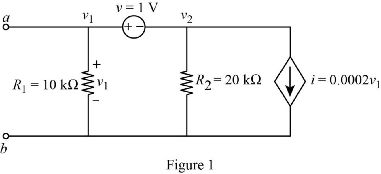
Refer to the redrawn Figure 1,
Apply Kirchhoff’s current law at node 1.
Here,
Substitute
Rearrange for
Rearrange for
Apply Kirchhoff’s voltage law between node 1 and 2.
Substitute
Rearrange for
So, the Thevenin voltage is
The redrawn circuit diagram is given in Figure 2,
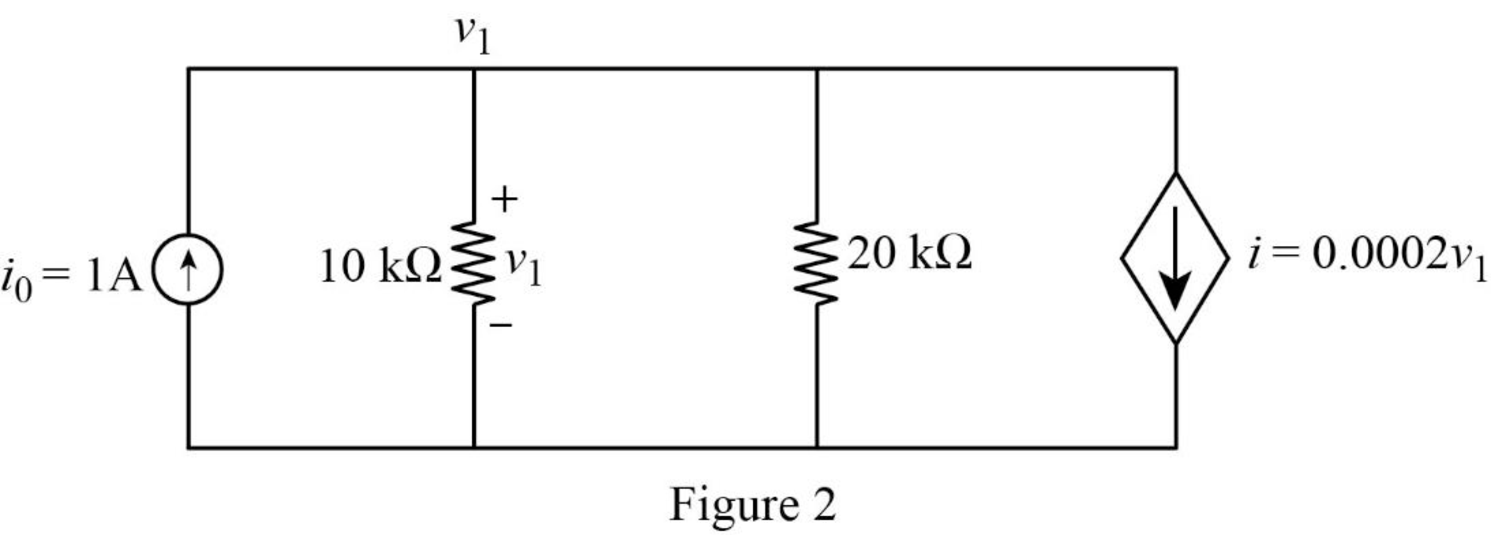
Refer to the redrawn Figure 2.
Apply Kirchhoff’s current law at node 1.
Here,
Substitute
Rearrange for
The expression for the Thevenin equivalent resistance is as follows,
Here,
Substitute
The redrawn circuit diagram is given in Figure 3,
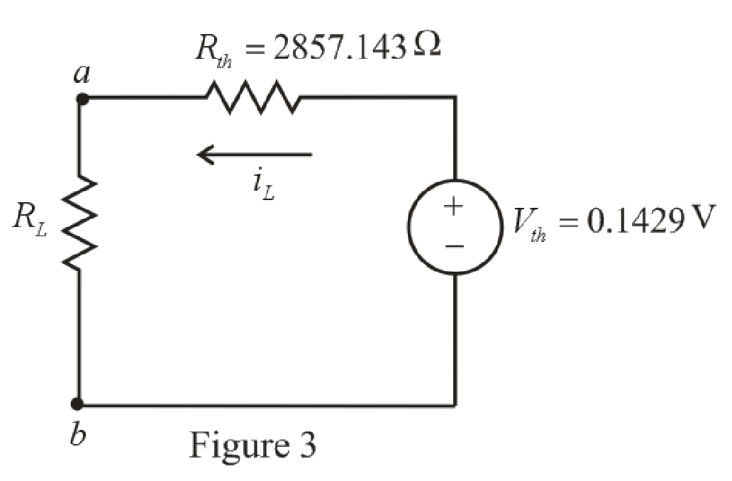
Refer to the redrawn Figure 3,
The expression for the current flowing in the circuit is as follows.
Here,
Substitute
Substitute
Conclusion:
Thus, the power dissipated by
(b)
The power dissipated by
(b)
Answer to Problem 41E
The power dissipated by
Explanation of Solution
Given Data:
The load resistance is
Calculation:
Refer to the redrawn Figure 3,
Substitute
Substitute
Conclusion:
Thus, the power dissipated by
(c)
The power dissipated by
(c)
Answer to Problem 41E
The power dissipated by
Explanation of Solution
Given Data:
The load resistance is
Calculation:
Refer to the redrawn Figure 3,
Substitute
Substitute
Conclusion:
Thus, the power dissipated by
Want to see more full solutions like this?
Chapter 5 Solutions
ENGINEERING CIRCUIT ANALYSIS ACCESS >I<


- If in the circuit of Example 5.5 the value of R, is doubled (to 13.1 k52), find approximate values for I, and V» Ans. 0.15 mA: 0.05 V Need workarrow_forward13- Amplifiers are used to increase the value of Resistance. Select one: True Falsearrow_forwardPlease design a transformer based charger works with 230V input and 5V output with N amp current.Number of turns in primary coil is M. Please calculate input current and number of turns in secondary coil.Assume device works with %100 efficiency.arrow_forward
- For each configuration in Fig. 5.85, find the individual (not combinations of) elements (voltages sources and/or resistors) that are in series. If necessary, use the fact that elements in series have the same current. Simply list those that satisfy the conditions for a series relationship.arrow_forwardCalculate input impedance Zwe of circuit with ideal transformed (Fig. 5.19). Assume: R=1Ω, XL=1Ω, XC=2Ω.arrow_forwardDetermine RTh and VTh at terminals 1-2 of each of the circuits of Fig. 4.arrow_forward
- You are installing a feeder to a 200 amp 3Phase/4 wire Panel board. What size conductors are you going to install, including the EGC. What size conduit will you install? How many amps are available at 120 volt for branch circuits?arrow_forwardKindly provide CLEAR and COMPLETE solutions #5arrow_forwardThe system of using helicopters to work on live power lines is based on the principle that electrical current seeks to flow into the ground. Select one: True Falsearrow_forward
- 1. Problem statements of the circuit to be designedarrow_forward1. A thyristor operating from a peak supply voltage of 400 V has the followingspecifications:Repetitive peak current, Ip = 200 A, = 50 A/µs, = 200 V/ µs. Choosing a factor safety forthe above-mentioned parameters, design a suitable snubber circuit. The minimum valueof load resistance is 10 Ω. 2. A boost converter with vin = 12 V is required to be designed for a 100 W rating. If theoutput voltage is maintained at 96 V, find out load resistance and duty ratio. Furtherdesign the filter components in consideration with a ripple of 10% and 5% in inputcurrent and output voltage. Take the switching frequency be 30 kHz. 3. Following are the specifications of a thyristor operating from a peak voltage supply of500 V: Repetitive peak current, Ip = 250 A, = 60 A/µs, = 200 V/µs. Take the factor ofsafety of 2 for the three specifications mentioned above. Design a suitable snubber circuitif the minimum load resistance is 20 Ω. Take ξ = 0.65. 4. A buck–boost converter operating at 20 kHz, L = 0.05 mH.…arrow_forward( NEED NEAT HANDWRITTEN SOLUTION ONLY OTHERWISE DOWNVOTE).In what region are these bipolar junction transistors working? for example my last 2 digit student number is 50.arrow_forward
 Introductory Circuit Analysis (13th Edition)Electrical EngineeringISBN:9780133923605Author:Robert L. BoylestadPublisher:PEARSON
 Delmar's Standard Textbook Of ElectricityElectrical EngineeringISBN:9781337900348Author:Stephen L. HermanPublisher:Cengage Learning
 Programmable Logic ControllersElectrical EngineeringISBN:9780073373843Author:Frank D. PetruzellaPublisher:McGraw-Hill Education
 Fundamentals of Electric CircuitsElectrical EngineeringISBN:9780078028229Author:Charles K Alexander, Matthew SadikuPublisher:McGraw-Hill Education
 Electric Circuits. (11th Edition)Electrical EngineeringISBN:9780134746968Author:James W. Nilsson, Susan RiedelPublisher:PEARSON
 Engineering ElectromagneticsElectrical EngineeringISBN:9780078028151Author:Hayt, William H. (william Hart), Jr, BUCK, John A.Publisher:Mcgraw-hill Education,