Fundamentals of Applied Electromagnetics (7th Edition)
7th Edition
ISBN: 9780133356984
Author: ULABY
Publisher: PEARSON
expand_more
expand_more
format_list_bulleted
Videos
Textbook Question
Chapter 5, Problem 41P
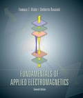
Determine the mutual inductance between the circular loop and the linear current shown in Fig. P5.41.
Expert Solution & Answer
Want to see the full answer?
Check out a sample textbook solution
Students have asked these similar questions
Consider a RC network made of one resistor and one capacitor in series.
Draw the charge stored in the capacitor and the current in the circuit as
function of time for both cases, charging and discharging.
In the circuit shown in the figure below the 20[pF] capacitor initially has a
charge of 3.5 [nc] on its plates. After the switch is closed, what will the
current in the circuit be when the capacitors have lost 80% of their initial
energy?
Hint: Work with the equations for i(t).
10.0 pF
20.0,
pF
非
15.0 pF
25.02
Figure 3
Exercise:
A square-wave voltage with amplitude 2 V and frequency 500 Hz is applied across
an ideal inductor. The inductance is 500 mH. Based on the mathematics discussed
above, we can say that the current will be a triangle-wave. What is the amplitude
of the triangle-wave current?
NAALINE
ersity Book
Q5. An inductor has a negligible resistance and an inductance of 200mH and is connected in
series with a 1 k resistor to a 24V d.c. supply. Determine the time constant of the circuit and
the steady state value of the current flowing in the circuit.
Find (a) the current flowing in the circuit at a time equal to one time constant,
(b) the voltage drop across the inductor at a time equal to two time constants and
(c) the voltage drop across the resistor after a time equal to three time constants.
Chapter 5 Solutions
Fundamentals of Applied Electromagnetics (7th Edition)
Ch. 5.1 - What are the major differences between the...Ch. 5.1 - Prob. 2CQCh. 5.1 - How is the direction of the magnetic moment of a...Ch. 5.1 - If one of two wires of equal length is formed into...Ch. 5.1 - An electron moving in the positive x direction...Ch. 5.1 - A proton moving with a speed of 2 106 m/s through...Ch. 5.1 - A charged particle with velocity u is moving in a...Ch. 5.1 - A horizontal wire with a mass per unit length of...Ch. 5.1 - A square coil of 100 turns and 0.5 m long sides is...Ch. 5.2 - Two infinitely long parallel wires carry currents...
Ch. 5.2 - Devise a right-hand rule for the direction of the...Ch. 5.2 - What is a magnetic dipole? Describe its magnetic...Ch. 5.2 - Prob. 6ECh. 5.2 - A wire carrying a current of 4 A is formed into a...Ch. 5.2 - Prob. 8ECh. 5.3 - What are the fundamental differences between...Ch. 5.3 - Prob. 9CQCh. 5.3 - Compare the utility of applying the BiotSavart law...Ch. 5.3 - Prob. 11CQCh. 5.3 - A current I flows in the inner conductor of a long...Ch. 5.3 - The metal niobium becomes a superconductor with...Ch. 5.5 - What are the three types of magnetic materials and...Ch. 5.5 - What causes magnetic hysteresis in ferromagnetic...Ch. 5.5 - Prob. 14CQCh. 5.5 - The magnetic vector M is the vector sum of the...Ch. 5.6 - With reference to Fig. 5-24, determine the single...Ch. 5.7 - Prob. 15CQCh. 5.7 - What is the difference between self-inductance and...Ch. 5.7 - Prob. 17CQCh. 5.7 - Use Eq. (5.89) to obtain an expression for B at a...Ch. 5 - An electron with a speed of 8 106 m/s is...Ch. 5 - When a particle with charge q and mass m is...Ch. 5 - The circuit shown in Fig. P5.3 uses two identical...Ch. 5 - The rectangular loop shown in Fig. P5.4 consists...Ch. 5 - In a cylindrical coordinate system, a 2 m long...Ch. 5 - Prob. 6PCh. 5 - Prob. 7PCh. 5 - Prob. 8PCh. 5 - The loop shown in Fig. P5.9 consists of radial...Ch. 5 - An infinitely long, thin conducting sheet defined...Ch. 5 - An infinitely long wire carrying a 25 A current in...Ch. 5 - Prob. 12PCh. 5 - Prob. 13PCh. 5 - Prob. 14PCh. 5 - A circular loop of radius a carrying current I1 is...Ch. 5 - Prob. 16PCh. 5 - Prob. 17PCh. 5 - Prob. 18PCh. 5 - Three long, parallel wires are arranged as shown...Ch. 5 - A square loop placed as shown in Fig. P5.20 has 2...Ch. 5 - Prob. 21PCh. 5 - Prob. 22PCh. 5 - Repeat Problem 5.22 for a current density J=zJ0er.Ch. 5 - In a certain conducting region, the magnetic field...Ch. 5 - Prob. 25PCh. 5 - Prob. 26PCh. 5 - Prob. 27PCh. 5 - A uniform current density given by J=zj0 (A/m2)...Ch. 5 - A thin current element extending between z = L/2...Ch. 5 - In the model of the hydrogen atom proposed by Bohr...Ch. 5 - Iron contains 8.5 1028 atoms/m3. At saturation,...Ch. 5 - The xy plane separates two magnetic media with...Ch. 5 - Given that a current sheet with surface current...Ch. 5 - In Fig. P5.34, the plane defined by x y = 1...Ch. 5 - The plane boundary defined by z = 0 separates air...Ch. 5 - Prob. 36PCh. 5 - Prob. 37PCh. 5 - A solenoid with a length of 20 cm and a radius of...Ch. 5 - Prob. 39PCh. 5 - The rectangular loop shown in Fig. P5.40 is...Ch. 5 - Determine the mutual inductance between the...
Knowledge Booster


Learn more about
Need a deep-dive on the concept behind this application? Look no further. Learn more about this topic, electrical-engineering and related others by exploring similar questions and additional content below.Similar questions
- A solenoid is to have an inductance of 0.285 mH, a cross-sectional area of 6.00x10⁻⁴ m2, and a length of 36.0cm. How many turns per unit length should it have? (Ans. 1.02x10³ turns/m) If the self-induced emf is -12.5 mV at a given time, at what rate is the current changing at that instant. (Ans. 43.9 A/s)arrow_forwardsolve the differential equationarrow_forwardExample-i ! A circuit is connected as shown in Fig. 5 to a 240V determine the current wave forms 50 HZ supply. Neglecting the diode volt-drop of the mean load voltage, and the mean load current for a load of (i) pure resistance of. 102 fii) an inductance of a H in series with a 102 resistor. Solution: √2x240 sinwt (~ figig load Voarrow_forward
- A spherical capacitor is filled with two dielectrics, as shown in the figure. Calculate the capacitance of the device. You must make a graph that represents the situation of the exercisearrow_forwardIn the circuit shown: a) Obtain the equivalent capacitance in pF b)Determine the charge Q1 (nC) at the capacitor C1. c) Determine the charge Q2 (nC) at the capacitor C2 d) Determine the charge Q4 (nC) at the capacitor C4. e) Solve the voltage (V) across C1. f) Solve the voltage (V) across C2 g) Solve the voltage (V) across C3 h) Solve the voltage (V) across C4arrow_forward4) Analyze the circuit given below to determine the charge stored in capacitor C4. C2 2uF C1 12UF C5 4uF C3 5uF C4 20uF 240Varrow_forward
- Both the Biot-Savart and Coulomb's laws exhibit an inverse-square relationship between field and source.? True O Falsearrow_forwardaj fariable capacitance and a resistance of 160 Q are connected in series alC r across a 240-V; 50-Hz supply. Draw the complex or locus of impedance and current as the capacitance changes from 4µF to 28 µF. From the diagram, find (a) the capacitance to give a current of 0.6 A and (b) the current when the capacitance is 11 µF.arrow_forwardQ5: Choose A A) A solid specimen of dielectric, dielectric constant of 4.5, shown in the figure has an internal void of thickness 1mm. The specimen is 1cm thick and is subjected to a voltage of 100 kV(rms). If the void is filled with air and if the breakdown strength of air can be taken as 35 kV(peak)/cm, find the voltage at which an internal discharge can occur. 11mm 10 mm 100KV (RMS)arrow_forward
arrow_back_ios
SEE MORE QUESTIONS
arrow_forward_ios
Recommended textbooks for you
 Introductory Circuit Analysis (13th Edition)Electrical EngineeringISBN:9780133923605Author:Robert L. BoylestadPublisher:PEARSON
 Delmar's Standard Textbook Of ElectricityElectrical EngineeringISBN:9781337900348Author:Stephen L. HermanPublisher:Cengage Learning
 Programmable Logic ControllersElectrical EngineeringISBN:9780073373843Author:Frank D. PetruzellaPublisher:McGraw-Hill Education
 Fundamentals of Electric CircuitsElectrical EngineeringISBN:9780078028229Author:Charles K Alexander, Matthew SadikuPublisher:McGraw-Hill Education
 Electric Circuits. (11th Edition)Electrical EngineeringISBN:9780134746968Author:James W. Nilsson, Susan RiedelPublisher:PEARSON
 Engineering ElectromagneticsElectrical EngineeringISBN:9780078028151Author:Hayt, William H. (william Hart), Jr, BUCK, John A.Publisher:Mcgraw-hill Education,
Introductory Circuit Analysis (13th Edition)
Electrical Engineering
ISBN:9780133923605
Author:Robert L. Boylestad
Publisher:PEARSON
Delmar's Standard Textbook Of Electricity
Electrical Engineering
ISBN:9781337900348
Author:Stephen L. Herman
Publisher:Cengage Learning
Programmable Logic Controllers
Electrical Engineering
ISBN:9780073373843
Author:Frank D. Petruzella
Publisher:McGraw-Hill Education
Fundamentals of Electric Circuits
Electrical Engineering
ISBN:9780078028229
Author:Charles K Alexander, Matthew Sadiku
Publisher:McGraw-Hill Education
Electric Circuits. (11th Edition)
Electrical Engineering
ISBN:9780134746968
Author:James W. Nilsson, Susan Riedel
Publisher:PEARSON
Engineering Electromagnetics
Electrical Engineering
ISBN:9780078028151
Author:Hayt, William H. (william Hart), Jr, BUCK, John A.
Publisher:Mcgraw-hill Education,
Types of Systems; Author: Neso Academy;https://www.youtube.com/watch?v=IRdDcSO_fQw;License: Standard youtube license