
Concept explainers
Videos
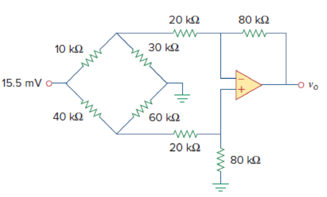
The circuit in Fig. 5.80 is a differential amplifier driven by a bridge. Find vo.
Calculate the output voltage
Answer to Problem 48P
The output voltage
Explanation of Solution
Given data:
Refer Figure 5.80 in the textbook for the differential amplifier that is driven by a bridge circuit.
Calculation:
Consider break this problem up into parts. The 15.5 mV voltage source splits the lower circuit from the upper circuit. In addition, there is no current flowing into the op amp input which means we now have the
Consider the expression for the current flows through the circuit.
Substitute 15.5 mV for
The voltage across the
Substitute
The voltage across the
This voltage is also the voltage at both inputs of the op amp and the voltage between the
Modify Figure 5.80 by indicating the node voltages. The modified figure as shown in Figure 1.
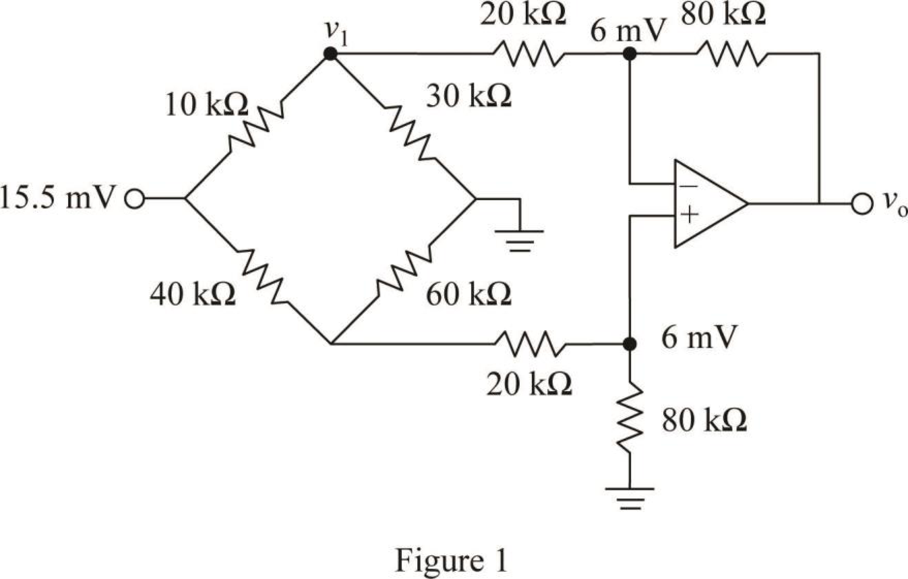
Write a node equation at node
Consider the expression for the current through the
Substitute 10.091 mV for
Write the expression for the output voltage
Substitute
Conclusion:
Thus, the output voltage
Want to see more full solutions like this?
Chapter 5 Solutions
Connect 2 Semester Access Card for Fundamentals of Electric Circuits


- The circuit in Fig. 5.79 is for a difference amplifier. Find vo given that v1 = 1 V and v2 = 2 V.arrow_forward5.40 Referring to the circuit shown in Fig. 5.77, determine Vo in terms of V1 and V2.arrow_forwarda) Design a noninverting amplifier (see Fig. 5.13) with a gain of 6. Assume the op amp is ideal. b) Suppose we wish to amplify a voltage vg, such that -1.5 V ... vg ... + 1.5 V. What are the smallest power supply voltages that could be used with the resistors selected in part (a) and still have the op amp in this design remain in its linear operating region?arrow_forward
- Let R = 2kOhm, given ideal resistors and op-amp calculate Vo(t) as a function of Va(t) and Vb(t).arrow_forward13- Amplifiers are used to increase the value of Resistance. Select one: True Falsearrow_forwardThe resistor Rf in the circuit attached is adjusted until the ideal op amp saturates. Specify Rf in kilo-ohms.arrow_forward
- Assuming an ideal op amp in circuit below, find Io.arrow_forwardQI:A: Design a multi-range ammeter of 0.5 and 1 Amp. using a PMMC(galvanometer) of 500 internal resistance and full-scale current of 1 ma. Show the way of connection with the load Rarrow_forwardPlease write down the meaning and functioning of the above amplifiersarrow_forward
- The resistor Rf in the circuit shown is adjusted until the ideal op amp saturates. Specify Rf in kilohms.arrow_forwardDraw a schematic of a 3 Stage Transistor amplifer with a Voltage gain of at least 50v/varrow_forwardBuild an instrumentation amplifier with differential gain varying between 300 and 1000.arrow_forward
 Introductory Circuit Analysis (13th Edition)Electrical EngineeringISBN:9780133923605Author:Robert L. BoylestadPublisher:PEARSON
 Delmar's Standard Textbook Of ElectricityElectrical EngineeringISBN:9781337900348Author:Stephen L. HermanPublisher:Cengage Learning
 Programmable Logic ControllersElectrical EngineeringISBN:9780073373843Author:Frank D. PetruzellaPublisher:McGraw-Hill Education
 Fundamentals of Electric CircuitsElectrical EngineeringISBN:9780078028229Author:Charles K Alexander, Matthew SadikuPublisher:McGraw-Hill Education
 Electric Circuits. (11th Edition)Electrical EngineeringISBN:9780134746968Author:James W. Nilsson, Susan RiedelPublisher:PEARSON
 Engineering ElectromagneticsElectrical EngineeringISBN:9780078028151Author:Hayt, William H. (william Hart), Jr, BUCK, John A.Publisher:Mcgraw-hill Education,