
EBK APPLIED STATICS AND STRENGTH OF MAT
6th Edition
ISBN: 8220101337603
Author: Spiegel
Publisher: YUZU
expand_more
expand_more
format_list_bulleted
Concept explainers
Videos
Textbook Question
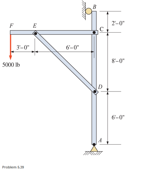
Chapter 5, Problem 5.39SP
A pin-connected crane framework is loaded and supported, as shown. The member weights are post, 700 Ib; boom, 800 Ib; and brace, 600 Ib. These weights may be considered to be acting at the midpoint of the respective members Calculate the pin reactions at pins A. B. C. D. and E.
Expert Solution & Answer
Want to see the full answer?
Check out a sample textbook solution
Students have asked these similar questions
For the frame shown, neglect the weight of the members and the frictionless pulleys, what is the horizontal component of the reaction at the hinge C? What is vertical component of the reaction at hinge C and D?
Using the method of members (analysis of frames), calculate the resultant pin reactions at A, B and D in the frame shown below. Neglect the weight of the members. Point A and D are pinned supports.
The rigid slab of weight W, with center of gravity at G. is suspended from three identical steel wires. Determine the force in each wire.
Chapter 5 Solutions
EBK APPLIED STATICS AND STRENGTH OF MAT
Ch. 5 - through 5.7 Calculate the forces in all members of...Ch. 5 - Calculate the forces in all members of the trusses...Ch. 5 - Calculate the forces in all members of the trusses...Ch. 5 - Calculate the forces in all members of the trusses...Ch. 5 - Calculate the forces in all members of the trusses...Ch. 5 - Calculate the forces in all members of the trusses...Ch. 5 - Calculate the forces in all members of the trusses...Ch. 5 - Determine the forces in members CD, DH, and HI for...Ch. 5 - Determine the forces in members BC, BE, and FE for...Ch. 5 - Determine the forces in members BC, CH, and CG in...
Ch. 5 - For the Howe roof truss shown, determine the...Ch. 5 - Determine the forces in members DE, CE, and BC in...Ch. 5 - Calculate the forces in members BC, BG, and FG for...Ch. 5 - Determine the forces in members CD, BD, BE, and CB...Ch. 5 - A pin-connected A-frame supports a load, as shown....Ch. 5 - Determine the pin reactions at pins A, B, and C in...Ch. 5 - Calculate the pin reactions at each of the pins in...Ch. 5 - A bracket is pin connected at points A, B, and D...Ch. 5 - A pin-connected frame is loaded, as shown....Ch. 5 - The cylinder shown has a mass of 500 kg. Determine...Ch. 5 - A simple frame is pin connected at points A, B,...Ch. 5 - Using the method of sections, determine the forces...Ch. 5 - Using the method of sections, determine the forces...Ch. 5 - through 5.31 Calculate the forces in all members...Ch. 5 - Calculate the forces in all members of the trusses...Ch. 5 - Calculate the forces in all members of the trusses...Ch. 5 - Calculate the forces in all members of the trusses...Ch. 5 - Calculate the forces in all members of the trusses...Ch. 5 - Calculate the forces in all members of the trusses...Ch. 5 - Calculate the forces in all members of the trusses...Ch. 5 - Calculate the forces in all members of the trusses...Ch. 5 - For Problems 5.32 through 5.38, calculate the...Ch. 5 - For Problem 5.32 through 5.38, Calculate the...Ch. 5 - For Problems 5.32 through 5.38, calculate the...Ch. 5 - For Problems 5.32 through 5.38, calculate the...Ch. 5 - For Problem 5.32 through 5.38 , Calculate the...Ch. 5 - For Problems 5.32 through 5.38, calculate the...Ch. 5 - For Problems 5.32 through 5.38, calculate the...Ch. 5 - A pin-connected crane framework is loaded and...Ch. 5 - Calculate the pin reactions at pins A, B, and D in...Ch. 5 - Determine the pin reactions at pins A, B, and C in...Ch. 5 - The wall bracket shown is pin-connected at points...Ch. 5 - Calculate the pin reactions at each of the pins in...Ch. 5 - The A-frame shown is pin-connected at A,B,C, and...Ch. 5 - The tongs shown are used to grip an object. For an...Ch. 5 - A toggle joint is a mechanism by which a...Ch. 5 - In the toggle joint of Problem 5.46 , assume that...Ch. 5 -
Knowledge Booster


Learn more about
Need a deep-dive on the concept behind this application? Look no further. Learn more about this topic, mechanical-engineering and related others by exploring similar questions and additional content below.Similar questions
- Compute the magnitude of the pin reaction at B. Neglect the weights of the structural members.arrow_forwardThe uniform bars AB and BC each weigh 4 lb/ft. Calculate the tension in cable DE, and the magnitudes of the ball-and-socket reactions at A, B, and C.arrow_forwardFind the force P required to (a) push; and (b) pull the 80-lb homogeneous roller over the 3-in. curb.arrow_forward
- Determine the roller reaction (in kN) at point A of the frame shown. (Show COMPLETE solutions in all the problems. FREE BODY DIAGRAMS ARE REQUIRED FOR EVERY PROBLEM BEFORE NUMERICAL SOLUTIONS. )arrow_forwardfrom the truss shown, find the force member BC and CG in kNarrow_forwardDetermine the force in members AC, BC, and BD of the truss shown in image by using method of section.arrow_forward
- The assembly shown is supported by pin supports at A and B, and consists of four members connected by pins at C, F, and D. Find the reaction forces and/or moments at points C, D, and F to support the 30 lb. and 40 lb. forces shown below.arrow_forwardQuestion 6 Neglecting the weights of the bar and the pulley and assuming the weight of the ball B to be 1467 N, calculate the reaction at the pin at A in N .arrow_forwardA 14m bar of negligible weight rest in a horizontal position on the smooth planes as shown. Compute the distance x at which load T = 250 kN should be placed from point B to keep the bar horizontal.arrow_forward
- Determine the angle for equilibrium of the lever shown in the figure. Disregard the weights of bars AB and BC.arrow_forwarddetermine the zero-force members in the truss shown.arrow_forwardFor the truss loaded and supported as shown in figure, determine the forces in member CD, DG and GH using method of sections.arrow_forward
arrow_back_ios
arrow_forward_ios
Recommended textbooks for you
 International Edition---engineering Mechanics: St...Mechanical EngineeringISBN:9781305501607Author:Andrew Pytel And Jaan KiusalaasPublisher:CENGAGE L
International Edition---engineering Mechanics: St...
Mechanical Engineering
ISBN:9781305501607
Author:Andrew Pytel And Jaan Kiusalaas
Publisher:CENGAGE L
Types Of loads - Engineering Mechanics | Abhishek Explained; Author: Prime Course;https://www.youtube.com/watch?v=4JVoL9wb5yM;License: Standard YouTube License, CC-BY