Videos
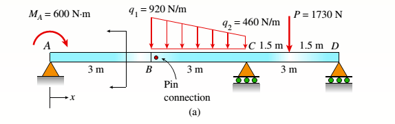
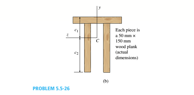
Consider the compound beam with segments AB and BCD joined by a pin connection (moment release) just right of B (see figure part a). The beam cross section is a double-T made up from three 50 mm × 150 mm wood members (actual dimensions, see figure part b),
(a) Find the cent raid C of the double-T cross section (c1:c2): then compute the moment of inertia, [I2 (mm4 )].
(b) Find the maximum tensile normal stress ifand maximum compressive normal stress tt. (kPa) for the loading shown. (Ignore the weight of the beam.)
(a)
The centroid
The moment of inertia of the section.
Answer to Problem 5.5.26P
The centroid
The moment of inertia of the section.
Explanation of Solution
Given information:
Width of the beam is
The following figure shows the distribution of forces on the beam
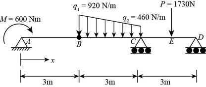
Figure-(1)
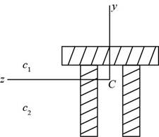
Figure-(2)
Write the expression for the distance of the centroid from the bottom.
Here, the for the distance of the centroid from the bottom is
Write the expression for the sum of centroids.
Here, the for the distance of the centroid from the top is
Write the expression for moment of inertia.
Here, the moment of inertia is
Calculation:
Substitute
Substitute
Substitute
Conclusion:
The centroid
The moment of inertia of the section
(b)
The maximum tensile normal stress.
The maximum compressive normal stress
Answer to Problem 5.5.26P
The maximum tensile normal stress is
The maximum compressive normal stress is
Explanation of Solution
The following figure shows the distribution of forces on the beam.
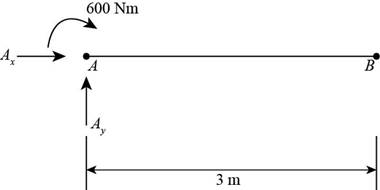
Figure-(3)
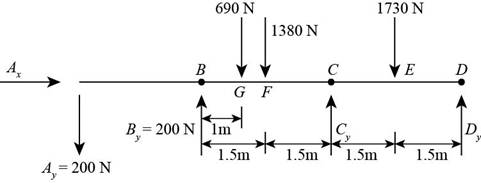
Figure-(4)
Write the expression for the moment about point
Here, the length of the member is
Write the expression for the vertical equilibrium of forces.
Here, the vertical reaction at point
Write the expression for moment at point
Here, the distance between the point
Write the expression for the vertical equilibrium of forces of free body
Here, the vertical reaction at point
Write the expression for the moment about point E
Here, the moment about point
Write the expression for the moment about point
Here, the moment about point
Write the expression for moment about point F
Here, the moment about point
Write the expression for moment about point
Here, the moment about point
Write the expression for moment about point
Here, the total moment about point
Write the expression for maximum tensile stress.
Here, the maximum tensile stress is
Calculation:
Substitute
Substitute
Substitute
Substitute
Substitute
Substitute
Substitute
Substitute
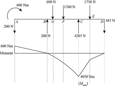
Figure-(5)
Substitute
Substitute
Conclusion:
The maximum tensile normal stress is
The maximum compressive normal stress is
Want to see more full solutions like this?
Chapter 5 Solutions
Mechanics of Materials - Text Only (Looseleaf)


- Beam ABC is fixed at support A and rests (at point B) upon the midpoint of beam DE (see part a of the figure). Thus, beam, ABC may be represented as a propped cantilever beam with an overhang BC and a linearly elastic support of stiffness k at point B (see part b of the figure). The distance from A to B is L = 10 ft, the distance from B to C is L/2 = 5 ft, and the length of beam DE is L = 10 ft. Both beams have the same flexural rigidity EI. A concentrated load P = 1700 lb acts at t lie free end of beam ABC. Determine the reactions RA, RB+ and MAfor beam ABC. Also, draw the shear-force and bending-moment diagrams for beam ABC, labeling all critical ordinates.arrow_forwardCantilever beam AB carries an upward uniform load of intensity q1from x = 0 to L/2 (see Fig. a) and a downward uniform load of intensity q from x = L/2 to L. Find q1in terms of q if the resulting moment at A is zero. Draw V and M diagrams for the case of both q and qtas applied loadings. Repeat part (a) for the case of an upward triangularly distributed load with peak intensity q0(see Fig. b). For part (b), find q0, instead of q1arrow_forwardA fixed-end beam AB of a length L is subjected to a uniform load of intensity q acting over the middle region of the beam (sec figure). Obtain a formula for the fixed-end moments MAand MBin terms of the load q, the length L, and the length h of the loaded part of the beam. Plot a graph of the fixed-end moment MAversus the length b of the loaded part of the beam. For convenience, plot the graph in the following nondimensional form: MAqL2/l2versusbL with the ratio b/L varying between its extreme values of 0 and 1. (c) For the special case in which ù = h = L/3, draw the shear-force and bending-moment diagrams for the beam, labeling all critical ordinates.arrow_forward
- A beam ABCD with a vertical arm CE is supported as a simple beam al A and D (see figure part a). A cable passes over a small pulley that is attached to the arm at E. One end of the cable is attached to the beam at point B. (a) What is the force P in the cable if the bending moment in the beam just lo the left of point C is equal numerically to 640 lb-ft? Note: Disregard the widths of the beam and vertical arm and use centerline dimensions when making calculations. (b) Repeat part (a) if a roller support is added at C and a shear release is inserted just left of C (see figure part b).arrow_forwardA beam made up all woun equal leg angles is subjected to a bending moment M having its vector .u an angle (i) lo lire axis (see figure paria). (a) For the position shown in lire figure, determine lire orienlalion of lire neulral axis and calculate lire maximum tensile s'av-s ir, and maximum compressive stress (b) The two angles are now inverted and attached back-lo-back lo lorn, a lintel beam that supports two courses of brick facade i see figure part b). Find the new orientation of the neutral axis and calculate the maximum tensile slress r. a::d maximum compressive s'avsrr . in I he beam using 6 = 30° and M = 30 kip-in.arrow_forwardA simple beam that is 18 ft long supports a uniform load of intensity q. The beam is constructed of two C8 x 11.5 sections (channel sections or C-shapes) on either side of a 4 × 8 (actual dimensions) wood beam (see the cross section shown in the figure part a). The modulus of elasticity of the steel (E; = 30,000 ksi) is 20 times that of the wood (Ew). (a) If the allowable stresses in the steel and wood are 12,000 psi and 900 psi, respectively, what is the allowable load qmax Note: Disregard the weight of the beam, and see Table F-3(a) of Appendix F for the dimensions and properties of the C-shape beam. (b) If the beam is rotated 90° to bend about its v axis (see figure part b) and uniform load q = 250 lb/ft is applied, find the maximum stresses trs and crw in the steel and wood, respectively Include the weight of the beam. (Assume weight densities of 35 lb/ft3 and 490 lb/ft3 for the wood and steel, respectively.)arrow_forward
- A beam with a guided support and 10-ft span supports a distributed load of intensity q = 660 lb/ft over its first half (see figure part a) and a moment Mq = 300 ft-lb at joint B. The beam consists of a wood member (nominal dimensions 6 in. x 12 in. and actual dimensions 5.5 in. x 11.5 in. in cross section, as shown in the figure part b) that is reinforced by 0.25-in.-thick steel plates on top and bottom. The moduli of elasticity for the steel and wood are £s = 30 X 106 psi and £"w = 1.5 X 10⁶ psi, respectively. Calculate the maximum bending stresses trs in the steel plates and rw in the wood member due to the applied loads. If the allowable bending stress in the steel plates is = 14,000 psi and that in the wood is (T.dV!= 900 psi, find qmiiX. (Assume that the moment at .fi, A/0, remains at 300 ft-lb.) If q = 660 lb/ft and allowable stress values in part (b) apply, what is Müm^ at B?arrow_forwardA wood beam 8 in. wide and 12 in. deep (nominal dimensions) is reinforced on top and bottom by 0,25-in.-thick steel plates (see figure part a), (a) Find the allowable bending moment A/max about the z axis if the allowable stress in the wood is 1100 psi and in the steel is 15,000 psi, (Assume that the ratio of the moduli of elasticity of steel and wood is 20.) (b) Compare the moment capacity of the beam in part a with that shown in the figure part b which has two 4 in. × 12 in, joists (nominal dimensions) attached to a 1/4 in, × 11.0 in, steel plate.arrow_forwardA fixed-end beam AB carries point load P acting at point C. The beam has a rectangular cross section (b = 75 mm, h = 150 mm). Calculate the reactions of the beam and the displacement at point C. Assume that E = 190 GPa.arrow_forward
- (a) A simple beam AB with length L and height h supports a uniform load of intensity q (see the figure part a). Obtain a formula for the curvature shortening A of this beam. Also, obtain a formula for the maximum bending stress b in the beam due to the load q. Now assume that the ends of the beam are pinned so that curvature shortening is prevented and a horizontal force H develops at the supports (see the figure part b). Obtain a formula for the corresponding axial tensile stress t . Using the formulas obtained in parts (a) and (b), calculate the curvature shortening , the maximum bending stress b, and the tensile stress t for the following steel beam: length L = 3m, height h = 300 mm, modulus of elasticity E = 200 GPa, and moment of inertia I = 36 x 106 mm4. Also, the load on the beam has intensity q = 25 kN/m. Compare the tensile stress tproduced by the axial forces with the maximum bending stress bproduced by the uniform load.arrow_forwardFrame ABCD carries two concentrated loads (2P at T and P at ZX see figure) and also a linearly varying distributed load on AB, Find expressions for shear force Fand moment A/at x = L/3 of beam AB in terms of peak load intensity q0, force P, and beam length variable L. Let q0= P/L.arrow_forwardA thin steel beam AB used in conjunction with an electromagnet in a high-energy physics experiment is securely bolted to rigid supports (see figure), A magnetic field produced by coils C results in a force acting on the beam. The force is trapezoidally distributed with maximum intensity q0= 18 kN/m. The length of the beam between supports is L = 200 mm, and the dimension c of the trapezoidal load is 50 mm. The beam has a rectangular cross section with width b = 60 and height h = 20 mm. Determine the maximum bending stress max and the maximum deflection for the beam. (Disregard any effects of axial deformations and consider only the effects of bending. Use E = 200 GPa.)arrow_forward
 Mechanics of Materials (MindTap Course List)Mechanical EngineeringISBN:9781337093347Author:Barry J. Goodno, James M. GerePublisher:Cengage Learning