
Videos
For the circuit shown in Figure P5.52, let
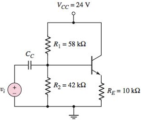
Figure P5.52
a.
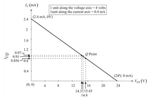
The ICQ and VCEQ and then sketching the load line and plotting the Q-point.
Answer to Problem 5.52P
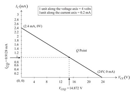
The ICQ and VCEQ :
ICQ =0.9128mA.
VCEQ =14.87V.
Explanation of Solution
Given:
The value of the attenuation factor,
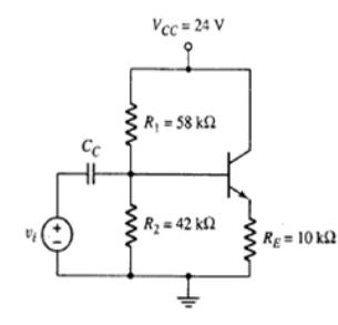
The circuit diagram is shown below:

The Thevenin resistance is evaluated as:
Applying the voltage division rule to evaluate the Thevenin voltage:
Redrawing the given circuit:
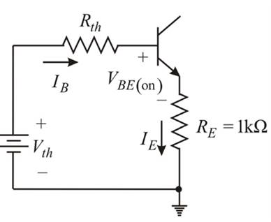
Applying the Kirchhoff’s voltage law in the base-emitter loop:
By the expression of the common emitter current gain:
The quiescent collector emitter voltage is given as:
Hence, the load line equation is given as:
The coordinates of the end points of the load line.
Since, VCE =0-V.
Hence,
Now, substituting IC =0A, then:
Hence, the coordinates of the two extremities of the load line is:
Sketching the load line graph:
b.
The range of the ICQ and VCEQ and plotting the various Q-point on the load line.
Explanation of Solution
Given:
The value of the attenuation factor,
The circuit diagram is shown below:
The resistor R1 and R2 vary by the
Now, evaluating the range of the resistor:
Now, evaluating the range of the R2:
Now taking
as R1 and R2 respectively:
Evaluating the Thevenin resistance using the equation 1:
Applying the voltage division rule to evaluate the Thevenin voltage using the equation 2:
By the use of the equation 3:
Now, from the equation 4:
Now taking
as R1 and R2 respectively:
Evaluating the Thevenin resistance using the equation 1:
Applying the voltage division rule to evaluate the Thevenin voltage using the equation 2:
By the use of the equation 3:
Now, from the equation 4:
Now taking
as R1 and R2 respectively:
Evaluating the Thevenin resistance using the equation 1:
Applying the voltage division rule to evaluate the Thevenin voltage using the equation 2:
By the use of the equation 3:
Now, from the equation 4:
Hence, the plot for the various Q points on the load line is:
Want to see more full solutions like this?
Chapter 5 Solutions
Microelectronics: Circuit Analysis and Design


- 5. In your own words, briefly describe the difference between the basic operation of a pchannel depletion-type MOSFET and p-channel Enhancement-type MOSFET.arrow_forwardDescribe step by step how MOSFET works and its applications.arrow_forwardGive two applications of nematic liquid crstalsarrow_forward
- Explore the advancements in microchip fabrication technology, including the transition from planar to FinFET transistors and the impact on power efficiency and performance.arrow_forwardFor the circuit shown, let IBIAS = 4 mA and RL = 500 Ohms. What is the value of VOUT?arrow_forwardHow do I tackle this circuit analysis problem?arrow_forward
- circuit shown in the figure, Kn = 2mA / V2, VIN = 0.7V for Mi mosfeti. So, what kind of relationship should there be between R1 and R2 resistance for mosfet to work at saturation?arrow_forwardDraw the block diagram of a HVDC converter station and briefly describe the function of each Component.Define LCC and VSC and compare their performancearrow_forwardDerive the expression for energy loss during the turnoff of the power transistorarrow_forward
- 2. We discussed in class how the channel capacitance can be modeled in different region of operations in MOSFETs. For your reference, the slide is shown below. Explain how you think the model would look like if a transistor is in velocity saturation region? Channel Capacitances Channel capacitance is a voltage dependent and non-linear capacitance S C P-sub Bulk Cutoff Region D Operation Region Cutoff Linear Saturation S P-sub Bulk C Linear Region CGBCH CoxWLeff 0 0 1 2 3 S P-sub Bulk Saturation Region CGSCH 0 сат CoxWL eff 1 2 CGDCH 0 CoxWLoft CoxWLoff eff D 0arrow_forwardDescribe the basic principle of operation of a bipolar junction transistor. Include explanation for the following : When minority carriers flow across the transistor Why the collector current is almost unaffected by the collector potentialarrow_forwardSolve the question using approximate methods, knowing that it gave the highest current, and through the Dc load line by half the current and voltage, we extract the value Ic & Vcearrow_forward
 Introductory Circuit Analysis (13th Edition)Electrical EngineeringISBN:9780133923605Author:Robert L. BoylestadPublisher:PEARSON
 Delmar's Standard Textbook Of ElectricityElectrical EngineeringISBN:9781337900348Author:Stephen L. HermanPublisher:Cengage Learning
 Programmable Logic ControllersElectrical EngineeringISBN:9780073373843Author:Frank D. PetruzellaPublisher:McGraw-Hill Education
 Fundamentals of Electric CircuitsElectrical EngineeringISBN:9780078028229Author:Charles K Alexander, Matthew SadikuPublisher:McGraw-Hill Education
 Electric Circuits. (11th Edition)Electrical EngineeringISBN:9780134746968Author:James W. Nilsson, Susan RiedelPublisher:PEARSON
 Engineering ElectromagneticsElectrical EngineeringISBN:9780078028151Author:Hayt, William H. (william Hart), Jr, BUCK, John A.Publisher:Mcgraw-hill Education,