Concept explainers
Videos
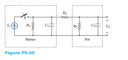
The burner and pot of Problem 5.54 can be modeled as shown in Figure P5.55.
a. Find the final temperature of the water in the pot—that is,find
b. How long will it take for the water to reach 80percent of its final temperature?
Hint: Neglect
Want to see the full answer?
Check out a sample textbook solution
Chapter 5 Solutions
Principles and Applications of Electrical Engineering


- Capacitance= 5uF1) Determine the time constant of the circuit for the capacities2) For the capacity value, calculate the estimated time to come to the final state.3) Plot capacitor current and voltage graphs and show if it works in harmony with the time constant you calculated. NOTE: if you want you can use falstad online circuit simulator.arrow_forwardSuppose we have a capacitance C discharging through a resistance R. Define and give an expression for the time constant. To attain a long time constant, do we need large or small values for R? For C?arrow_forwardAssuming that a nonzero ac voltage source is applied, what can you say about whether the power and reactive power are positive, negative, or zero for a pure capacitance in series with a pure inductance? Consider cases in which the impedance magnitude of the capacitance is greater than, equal to, or less than the impedance magnitude of the inductance. Repeat Problem P5.74 for the inductance and capacitance in parallel.arrow_forward
- a) Find the final value for the capacitor voltage (Vc(∞ ))? b) Find the circuit time constant for t>0? c) Find an expression for the capcitor voltage for t>0?arrow_forwardA resistor, an inductor, and a capacitor are connected in parallel to an ac source with voltage amplitude V and angular frequency v. Let the source voltage be given by v = Vcosvt. (a) Show that each of the instantaneous voltages vR, vL, and vC at any instant is equal to v and that i = iR + iL + iC, where i is the current through the source and iR, iL, and iC are the currents through the resistor, inductor, and capacitor, respectively. (b) What are the phases of iR, iL, and iC with respect to v? Use current phasors to represent i, iR, iL, and iC. In a phasor diagram, show the phases of these four currents with respect to v. (c) Use the phasor diagram of part (b) to show that the current amplitude I for the current i through the source is I = √(I2R) + (IC - IL)2 . (d) Show that the result of part (c) can be written as I = V/Z, with 1/Z = √ (1/R2) + [ωC - (1/ωL)]2.arrow_forwardThe current shown below is applied to a 0.25??capacitor. The initial voltage on the capacitor is zero.a) Find the charge on the capacitor at ?=15??.b) Find the voltage on the capacitor at ?=30??c) How much energy is stored in the capacitor by this current?arrow_forward
- The Thévenin equivalent of a two-terminal network is shown in Figure P5.93. The frequency is f=60 Hz. We wish to connect a load across terminals that consists of a resistance and a capacitance in series such that the power delivered to the resistance is maximized. Find the value of the resistance and the value of the capacitance. Repeat Problem P5.93 with the load required to consist of a resistance and a capacitance in parallel.arrow_forwardA solid specimen of dielectric dielectric constant of 4.0, shown in the figure has an internal void of thickness 1mm. The specimen is 1cm thick and is subjected to a voltage of 80 kV(rms). If the void is filled with air and if the breakdown strength of air can be taken as 30 kV(peak)/cm, find the voltage at which an internal dischargearrow_forwardDescribe the steady-state similarities and differences of DC and AC circuits with purelyresistive elementsarrow_forward
- Solve for the node voltage shown in Figure P5.54.arrow_forwardA lossy capacitor Cx, rated for operation of 5 kV, 50 Hz is represented by an equivalent circuit with an ideal capacitor Cp in parallel with a resistor Rp. Cp is 0.102 microF and Rp=1.25 Mohm. The power loss, and loss tangent of this lossy capacitor at rated voltage respectively ?arrow_forwarda) We assume that the switch is on. Calculate the reactance values and find the charging current in the circuit below. Is the circuit capacitive or inductive? Show that the voltage across the capacitance can be slightly larger than the source voltage U. (This is called the Ferranti effect and means that we can get a voltage rise beyond overhead lines with small loads. This is mostly relevant at the highest voltage levels. The frequency f is 50Hz, and assume voltage U= √2⋅24kVarrow_forward
 Introductory Circuit Analysis (13th Edition)Electrical EngineeringISBN:9780133923605Author:Robert L. BoylestadPublisher:PEARSON
 Delmar's Standard Textbook Of ElectricityElectrical EngineeringISBN:9781337900348Author:Stephen L. HermanPublisher:Cengage Learning
 Programmable Logic ControllersElectrical EngineeringISBN:9780073373843Author:Frank D. PetruzellaPublisher:McGraw-Hill Education
 Fundamentals of Electric CircuitsElectrical EngineeringISBN:9780078028229Author:Charles K Alexander, Matthew SadikuPublisher:McGraw-Hill Education
 Electric Circuits. (11th Edition)Electrical EngineeringISBN:9780134746968Author:James W. Nilsson, Susan RiedelPublisher:PEARSON
 Engineering ElectromagneticsElectrical EngineeringISBN:9780078028151Author:Hayt, William H. (william Hart), Jr, BUCK, John A.Publisher:Mcgraw-hill Education,