
Videos
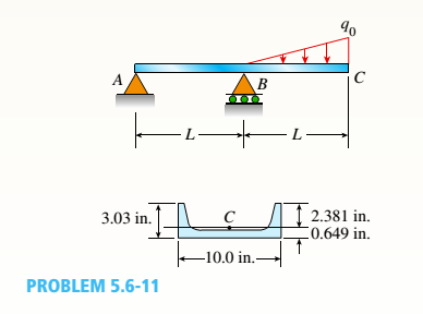
A beam ABC with an overhang from B to C is constructed of a C 10 × 30 channel section with flanges facing upward (sec figure). The beam supports its own weight (30 lb/ft) plus a triangular load of maximum intensity g0 acting on the overhang. The allowable stresses in tension and compression arc IS ksi and 12 ksi, respectively.
- Determine the allowable triangular load intensity allow if tne distance L equals 4 ft.
(a)
The allowable triangular load intensity.
Answer to Problem 5.6.11P
The allowable triangular load intensity is
Explanation of Solution
Given information:
The weight of the beam is
The following figure shows the free body diagram.
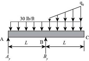
Figure-(1)
Write the expression for the moment about point
Here, the vertical reaction on point
Write the expression for the equilibrium forces at point
Here, the vertical reaction on point
Write the expression for the maximum moment at point
Here, the maximum moment is
Write the expression for the allowable bending moment based on tension.
Here, maximum tensile stress is
Write the expression for the allowable bending moment based on compression.
Here, maximum compressible stress is
Write the expression for the load intensity of triangular load considering tension.
Write the expression for the load intensity of triangular load considering compression.
Calculation:
Substitute
Substitute
Substitute
Substitute
Substitute
Substitute
Conclusion:
The allowable triangular load intensity is
(b)
The allowable triangular load intensity when the beam is rotated
Answer to Problem 5.6.11P
The allowable triangular load intensity when the beam is rotated
Explanation of Solution
Write the expression for the allowable bending moment based on tension.
Write the expression for the allowable bending moment based on compression.
Write the expression for the load intensity of triangular load considering tension.
Write the expression for the load intensity of triangular load considering compression.
Calculation:
Substitute
Substitute
Substitute
Substitute
Conclusion:
The allowable triangular load intensity when the beam is rotated
Want to see more full solutions like this?
Chapter 5 Solutions
Bundle: Mechanics Of Materials, Loose-leaf Version, 9th + Mindtap Engineering, 2 Terms (12 Months) Printed Access Card


- A cantilever beam AB of length L = 6 It is constructed of a W 8 x 21 wide-flange section (see figure), A weight W = 1500 lb falls through a height h = 0.25 in. onto the end of the beam. Calculate the maximum deflection £m.iy of the end of the beam and the maximum bendini* stress *rm,vdue to the falling weight, (Assume E = 30 X 10 psi,)arrow_forwardA W 12 x 35 steel cantilever beam is subjected to an axial load P = 10 kips and a transverse load V = 15 kips. The beam has length L = 6 ft, (a) Calculate the principal normal stresses and the maximum shear stress for an clement located at C near the fixed support. Neglect the weight of the beam, (b) Repeat Part a for point D which is 4 in. above point C (see figure). See Table F-l(a), Appendix F, for beam properties.arrow_forwardA W 12 x 50 steel wide-flange beam and a segment of a 4-inch thick concrete slab (see figure) jointly resist a positive bending moment of 95 kip-ft. The beam and slab are joined by shear connectors that are welded to the steel beam. (These connectors resist the horizontal shear at the contact surface.) The moduli of elasticity of the steel and the concrete are in the ratio 12 to 1. Determine the maximum stresses r1 and xtin the steel and concrete, respectively. Note: See Table F-l(a) of Appendix F for the dimensions and properties of the steel beam.arrow_forward
- Solve the preceding problem for a wide-flange beam with h = 404 mm, b = 140 mm, bf= 11.2 mm, and rf. = 6.99 mm.arrow_forwardA cantilever beam AB of length L = 6.5 ft supports a trapezoidal distributed load of peak intensity 4, and minimum intensity q/2tthat includes the weight of the beam (see figure). The beam is a steel W 12 × 14 wide-flange shape (see Table F-l(a), Appendix F). Calculate the maximum permissible load q based upon (a) an allowable bending stress eallow = 18 ksi and (b) an allowable shear stress eallow = 7,5 ksi. Note: Obtain the moment of inertia and section modulus of the beam from Table F-l(a).arrow_forwardSolve the preceding problem for a box beam with dimensions h = 0.5 m, h = 0.18 m, and t = 22 mm. The yield stress of the steel is 210 MPa.arrow_forward
- A propped cantilever beam of length L = 54 in. with a sliding support supports a uniform load of intensity q (see figure). The beam is made of steel {<7y = 36 ksi) and has a rectangular cross section of width/) = 4.5 in. and height h = 6.0 in. What load intensity q will produce a fully plastic condition in the beam?arrow_forwardA hollow box beam with height h = 9.5 in., inside height/i, = 8.0 in., width? = 5,25 in., and inside width =4.5 in. is shown in the figure. Assuming that the beam is constructed of steel with yield stress ty= 42 ksi calculate the yield moment My, plastic moment MPand shape factor f.arrow_forwardA reinforced concrete slab (see figure) is reinforced with 13-mm bars spaced 160 mm apart at d = 105 mm from the top of the slab. The modulus of elasticity for the concrete is Ec= 25 GPa, while that of the steel is £s = 200 G Pa. Assume that allowable stresses for concrete and steel arecrac = 9.2 MPa and us = 135 MPa. l()5 mm Find the maximum permissible positive bending moment for a l-m wide strip of the slab. What is the required area of steel reinforcement, A^ if a balanced condition must be achieved? What is the allowable positive bending moment? (Recall that in a balanced design, both steel and concrete reach allowable stress values simultaneously under the design moment.)arrow_forward
- A simple beam that is 18 ft long supports a uniform load of intensity q. The beam is constructed of two C8 x 11.5 sections (channel sections or C-shapes) on either side of a 4 × 8 (actual dimensions) wood beam (see the cross section shown in the figure part a). The modulus of elasticity of the steel (E; = 30,000 ksi) is 20 times that of the wood (Ew). (a) If the allowable stresses in the steel and wood are 12,000 psi and 900 psi, respectively, what is the allowable load qmax Note: Disregard the weight of the beam, and see Table F-3(a) of Appendix F for the dimensions and properties of the C-shape beam. (b) If the beam is rotated 90° to bend about its v axis (see figure part b) and uniform load q = 250 lb/ft is applied, find the maximum stresses trs and crw in the steel and wood, respectively Include the weight of the beam. (Assume weight densities of 35 lb/ft3 and 490 lb/ft3 for the wood and steel, respectively.)arrow_forwardA wood beam in a historic theater is reinforced with two angle sections at the outside lower corners (see figure). If the allowable stress in the wood is 12 M Pa and that in the steel is 140 M Pa, what is ratio of the maximum permissible moments for the beam before and after reinforcement with the angle sections? See Appendix F Table F-5(b) for angle section properties. Assume that ew= 12 GPa and E3=210 GPa.arrow_forwardThe hollow box beam shown in the figure is subjected to a bending moment M of such magnitude that the flanges yield but the webs remain linearly elastic. (a) Calculate the magnitude of the moment M if the dimensions of the cross section are A = 15 in., A] = 12.75 in., h = 9 in., and ey =7.5 in. Also, the yield stress is eY = 33 ksi. (b) What percent of the moment M is produced by the elastic core?arrow_forward
 Mechanics of Materials (MindTap Course List)Mechanical EngineeringISBN:9781337093347Author:Barry J. Goodno, James M. GerePublisher:Cengage Learning