EBK STRUCTURAL ANALYSIS
5th Edition
ISBN: 9780100469105
Author: KASSIMALI
Publisher: YUZU
bartleby

Concept explainers

Question
Book Icon
Chapter 5, Problem 61P
To determine

Plot the shear diagram, bending moment diagram, axial force diagram, and the qualitative deflected shape of the frame.

Expert Solution & Answer
Check Mark

Explanation of Solution

Write the condition for static instability, determinacy and indeterminacy of plane frames as follows:

3m+r<3j+ecstaticallyunstableframe        (1)

3m+r=3j+ecstaticallydeterminateframe        (2)

3m+r>3j+ecstaticallyindeterminateframe        (3)

Here, number of members is m, number of external reactions is r, the number of joints is j, and the number of elastic hinges is ec.

Find the degree of static indeterminacy (i) using the equation;

i=(3m+r)(3j+ec)        (4)

Refer to the Figure in the question;

The number of members (m) is 2.

The number of external reactions (r) is 3.

The number of joints (j) is 3.

The number of elastic hinges ec is 0.

Substitute the values in Equation (2);

3(2)+3=3(3)+09=9staticallydeterminateframe

Show the free-body diagram of the entire frame as in Figure 1.
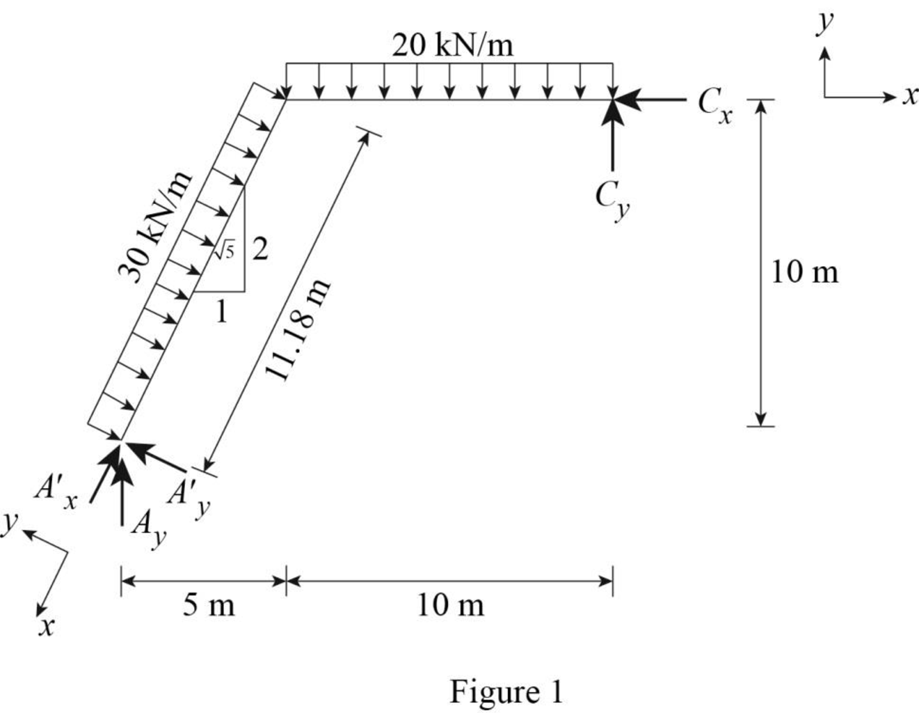
EBK STRUCTURAL ANALYSIS, Chapter 5, Problem 61P , additional homework tip  1

Refer Figure (1).

Find the distance for the beam AB.

ABsinθ=10AB=10sin63.43°AB=11.18m

Find the horizontal reaction at point C by resolving the horizontal component of forces.

+FX=0Cx+30×11.18×25=0Cx=300kN()

Find the resultant reaction at point C by taking moment about point A.

+MA=0Cy(15)20(10)(102+5)+300(10)30×11.18×11.182=015Cy2,000+3,0001,874.886=0Cy=58.33kN()

Find the vertical reaction at point A by resolving the vertical component of forces.

+FY=0Ay20×1030×11.18×15+Cy=0Ay200149.99+58.33=0Ay=291.66kN()

Consider point A:

Resolve the vertical component of forces.

+FY=0Ay=Ay(15)=291.66(15)=130.4kN

Resolve the horizontal component of forces.

+FX=0Ax=Ay(25)=291.66(25)=260.87kN()

Show the free-body diagram of the members and joints of the entire frame as in Figure 2.
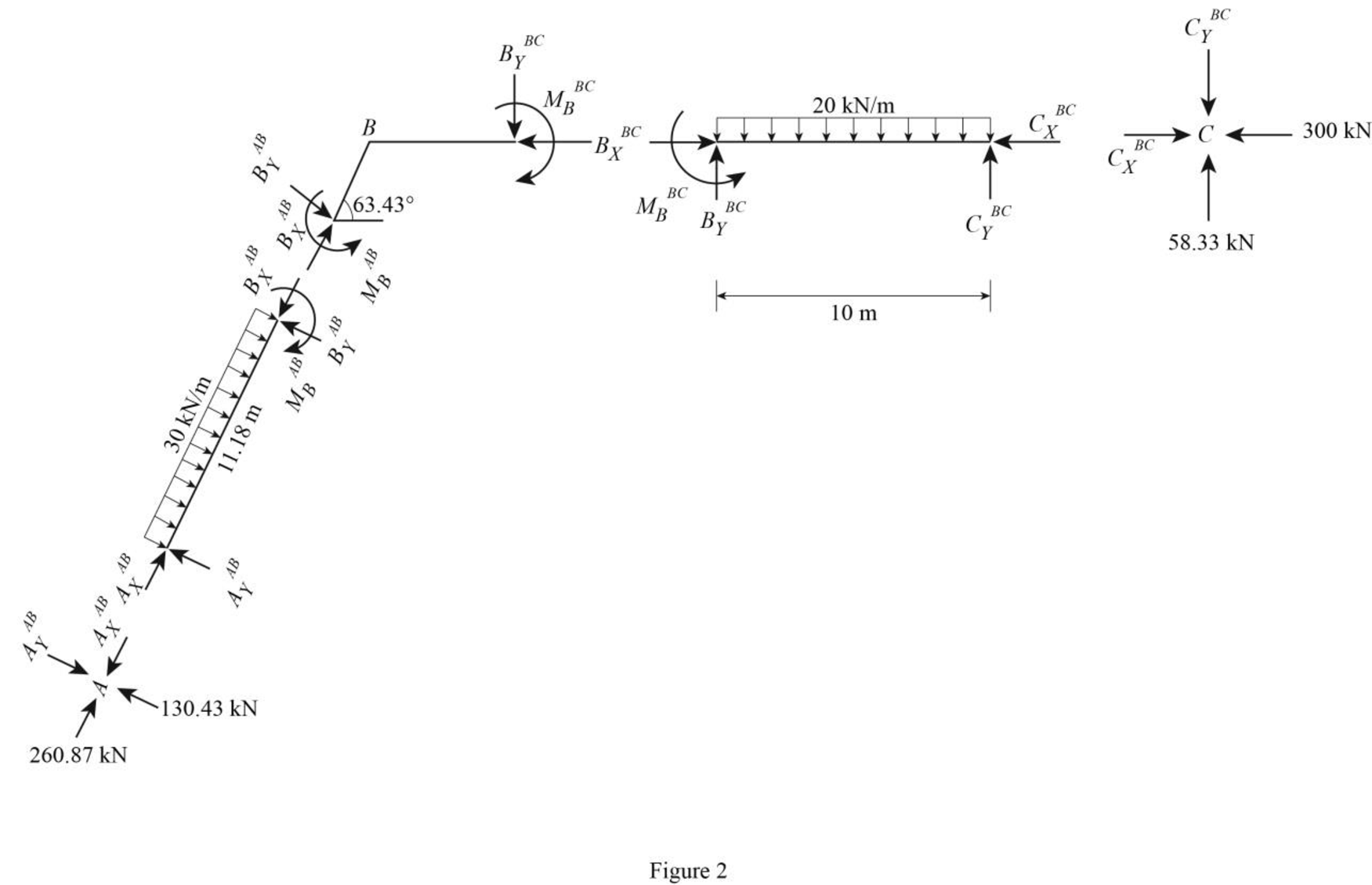
EBK STRUCTURAL ANALYSIS, Chapter 5, Problem 61P , additional homework tip  2

Consider point A:

Resolve the vertical component of forces.

+FY=0130.4AYBC=0AYBC=130.4kN

Resolve the horizontal component of forces.

+FX=0260.87AXBC=0AXBC=260.87kN

Consider the member AB:

Resolve the vertical component of forces.

+FY=0AYAB30×11.18+BYAB=0130.43335.4+BYAB=0BYAB=204.97kN

Resolve the horizontal component of forces.

+FX=0BXAB+AXAB=0BXBC+260.87=0BXBC=260.87kN

Take moment about the point B.

+MBAB=0AYAB(11.18)+30×11.18(11.182)MBAB=0130.43(11.18)+450MBAB=0MBAB=416.67kNm

Consider the point C:

Resolve the vertical component of forces.

+FY=058.33CYBC=0CYBC=58.33kN

Resolve the horizontal component of forces.

+FX=0300+CXBC=0CXBC=300kN

Consider the member BC:

Resolve the vertical component of forces.

+FY=0BYBC20×10+CYBC=0BYBC200+58.33=0BYBC=141.67kN

Resolve the horizontal component of forces.

+FX=0BXBCCXBC=0BXBC300=0BXBC=300kN

Take moment about point B:

+MBBC=0CYBC(10)20×10(102)+MBBC=058.33(10)1,000+MBBC=0MBBC=416.7kNm

Plot the moment end forces of the frame as in Figure 3.

EBK STRUCTURAL ANALYSIS, Chapter 5, Problem 61P , additional homework tip  3

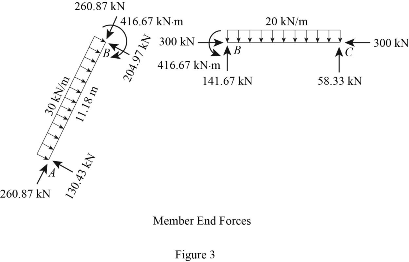
Refer to the moment end force diagram plot the shear diagram, bending moment diagram, and the axial force diagrams.

Plot the shear force diagram as in Figure 4.

EBK STRUCTURAL ANALYSIS, Chapter 5, Problem 61P , additional homework tip  4

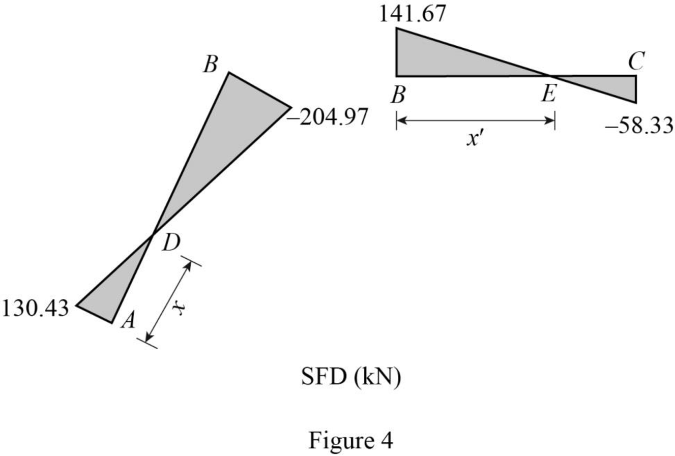
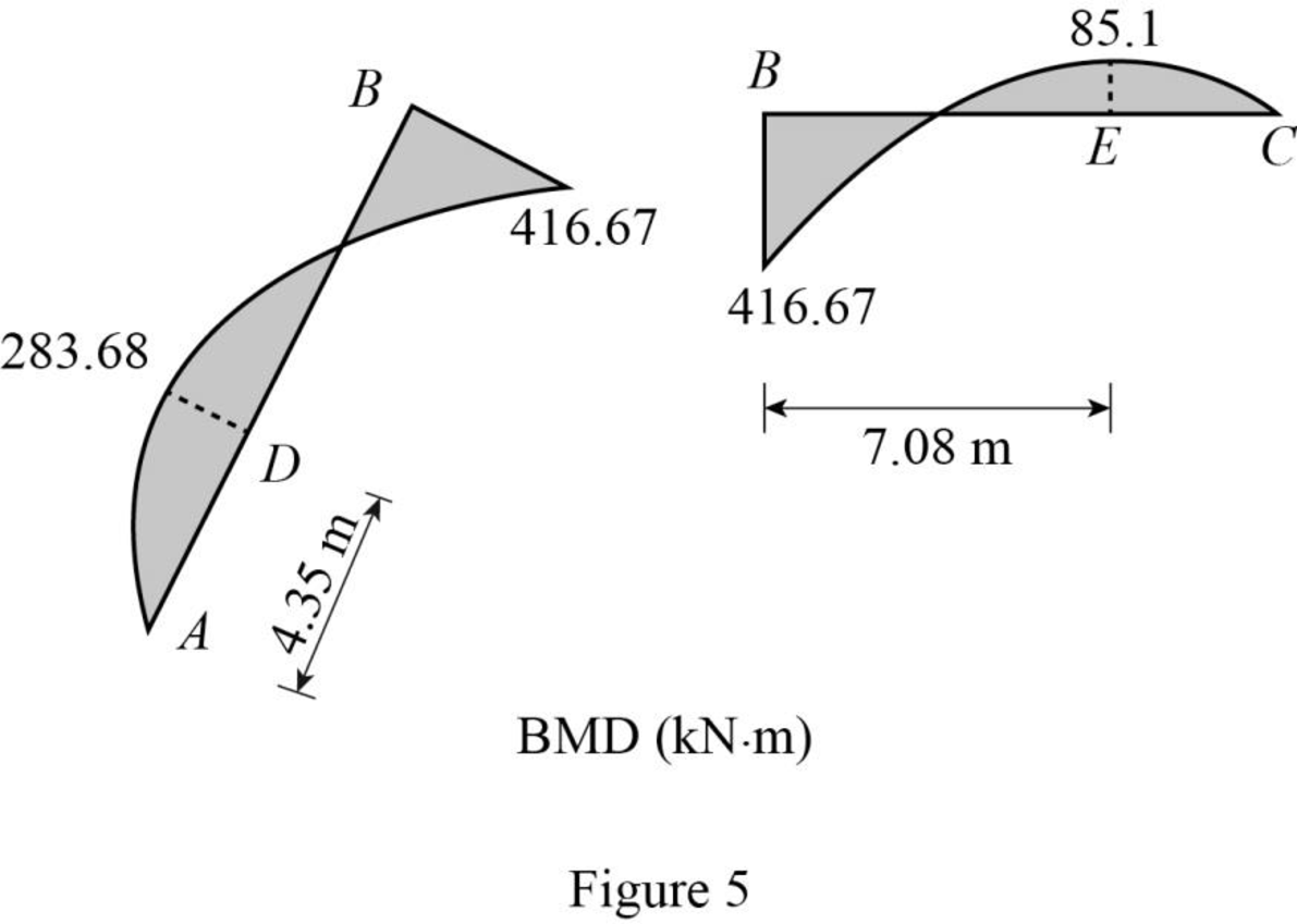
The maximum bending moment occurs where the shear force changes sign.

Consider the section ADB, use the similar triangle concept.

130.44x=204.9711.18x1,458.32130.44x=204.97x335.41x=1,458.32x=4.35mfrompoint A

Find the maximum bending at point D.

MD=130.43×4.352=283.68kNm

Consider the section BEC, use the similar triangle concept.

141.67x=58.3310x1,416.7141.67x=58.33x200x=1,416.7x=7.08mfrompoint B

Find the maximum bending at point D.

MD=58.33×(107.08)2=85.1kNm

Plot the bending moment diagram as in Figure 5.

EBK STRUCTURAL ANALYSIS, Chapter 5, Problem 61P , additional homework tip  5

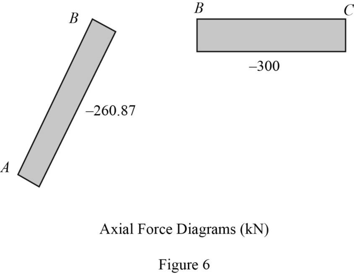
Plot the axial force diagram as in Figure 6.

EBK STRUCTURAL ANALYSIS, Chapter 5, Problem 61P , additional homework tip  6

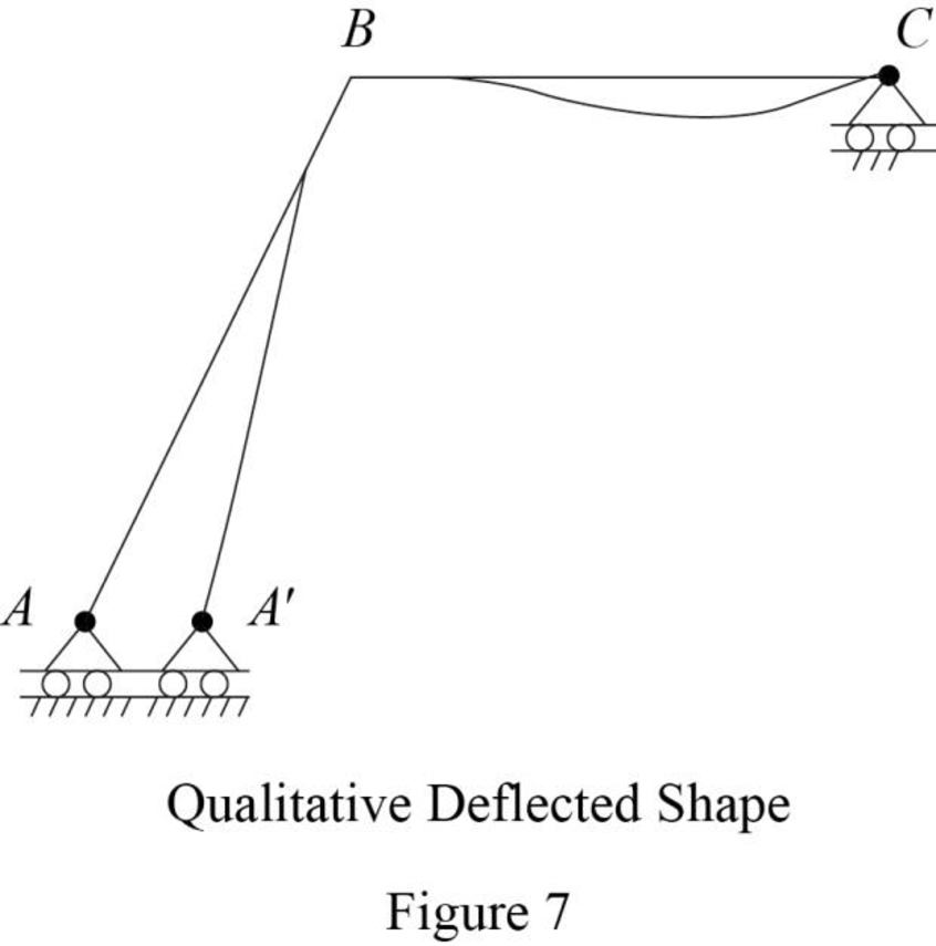
Plot the qualitative deflected shape as in Figure 7.

EBK STRUCTURAL ANALYSIS, Chapter 5, Problem 61P , additional homework tip  7

Want to see more full solutions like this?

Subscribe now to access step-by-step solutions to millions of textbook problems written by subject matter experts!
Students have asked these similar questions
Draw the shear and bending moment diagrams and the qualitative deflected shape for the beam shown in Fig. 5.13(a).
Analysis of Frames with Shear and Moment Diagram, P=84
Gate AB in fig.4 is a quarter of circle 6m wide into the paper. Find the force Fjust sufficient to prevent rotation about hinge B. Neglect the weight of the gate.

Chapter 5 Solutions

EBK STRUCTURAL ANALYSIS

Ch. 5 - Prob. 11PCh. 5 - Determine the equations for shear and bending...Ch. 5 - Determine the equations for shear and bending...Ch. 5 - Determine the equations for shear and bending...Ch. 5 - Determine the equations for shear and bending...Ch. 5 - Determine the equations for shear and bending...Ch. 5 - Prob. 17PCh. 5 - Determine the equations for shear and bending...Ch. 5 - 5.12 through 5.28 Determine the equations for...Ch. 5 - 5.12 through 5.28 Determine the equations for...Ch. 5 - 5.12 through 5.28 Determine the equations for...Ch. 5 - 5.12 through 5.28 Determine the equations for...Ch. 5 - 5.12 through 5.28 Determine the equations for...Ch. 5 - 5.12 through 5.28 Determine the equations for...Ch. 5 - Prob. 25PCh. 5 - 5.12 through 5.28 Determine the equations for...Ch. 5 - Prob. 27PCh. 5 - 5.12 through 5.28 Determine the equations for...Ch. 5 - Prob. 29PCh. 5 - Prob. 30PCh. 5 - 5.29 through 5.51 Draw the shear and bending...Ch. 5 - 5.29 through 5.51 Draw the shear and bending...Ch. 5 - 5.29 through 5.51 Draw the shear and bending...Ch. 5 - Prob. 34PCh. 5 - 5.29 through 5.51 Draw the shear and bending...Ch. 5 - Prob. 36PCh. 5 - 5.29 through 5.51 Draw the shear and bending...Ch. 5 - 5.29 through 5.51 Draw the shear and bending...Ch. 5 - Prob. 39PCh. 5 - Prob. 40PCh. 5 - 5.29 through 5.51 Draw the shear and bending...Ch. 5 - 5.29 through 5.51 Draw the shear and bending...Ch. 5 - 5.29 through 5.51 Draw the shear and bending...Ch. 5 - Prob. 44PCh. 5 - Prob. 45PCh. 5 - 5.29 through 5.51 Draw the shear and bending...Ch. 5 - 5.29 through 5.51 Draw the shear and bending...Ch. 5 - 5.29 through 5.51 Draw the shear and bending...Ch. 5 - 5.29 through 5.51 Draw the shear and bending...Ch. 5 - 5.29 through 5.51 Draw the shear and bending...Ch. 5 - 5.29 through 5.51 Draw the shear and bending...Ch. 5 - Draw the shear and bending moment diagrams for the...Ch. 5 - For the beam shown: (a) determine the distance a...Ch. 5 - For the beam shown: (a) determine the distance a...Ch. 5 - Prob. 55PCh. 5 - Prob. 56PCh. 5 - Prob. 57PCh. 5 - Prob. 58PCh. 5 - Prob. 59PCh. 5 - Prob. 60PCh. 5 - Prob. 61PCh. 5 - Prob. 62PCh. 5 - Prob. 63PCh. 5 - Prob. 64PCh. 5 - Prob. 65PCh. 5 - Prob. 66PCh. 5 - Prob. 67PCh. 5 - Prob. 68PCh. 5 - Prob. 69PCh. 5 - Prob. 70PCh. 5 - Prob. 71P
Knowledge Booster
Background pattern image
Civil Engineering
Learn more about
Need a deep-dive on the concept behind this application? Look no further. Learn more about this topic, civil-engineering and related others by exploring similar questions and additional content below.
Recommended textbooks for you
  • Text book image
    Structural Analysis
    Civil Engineering
    ISBN:9781337630931
    Author:KASSIMALI, Aslam.
    Publisher:Cengage,
Text book image
Structural Analysis
Civil Engineering
ISBN:9781337630931
Author:KASSIMALI, Aslam.
Publisher:Cengage,