
Concept explainers
Plot the shear diagram, bending moment diagram, axial force diagram, and the qualitative deflected shape of the frame.
Explanation of Solution
Write the condition for static instability, determinacy and indeterminacy of plane frames as follows:
Here, number of members is m, number of external reactions is r, the number of joints is j, and the number of elastic hinges is
Find the degree of static indeterminacy (i) using the equation;
Refer to the Figure in the question;
The number of members (m) is 3.
The number of external reactions (r) is 6.
The number of joints (j) is 4.
The number of elastic hinges
Substitute the values in Equation (2);
Show the free-body diagram of the entire frame as in Figure 1.
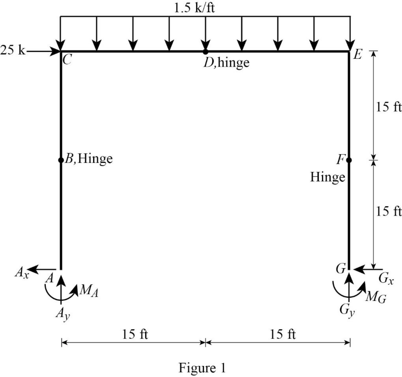
Refer Figure 1,
Consider the section BCDEFG:
Take moment about point B:
Consider the section DEFG:
Take moment about point D:
Consider the section FG:
Take moment about point F:
Solve the Equations (1), (2), and (3) simultaneously.
Consider entire frame:
Find the vertical reaction at point A by resolving the vertical component of forces.
Find the moment at point A by taking moment about point A.
Find the horizontal reaction at point A by resolving the horizontal component of forces.
Show the free-body diagram of the members and joints of the entire frame as in Figure 2.
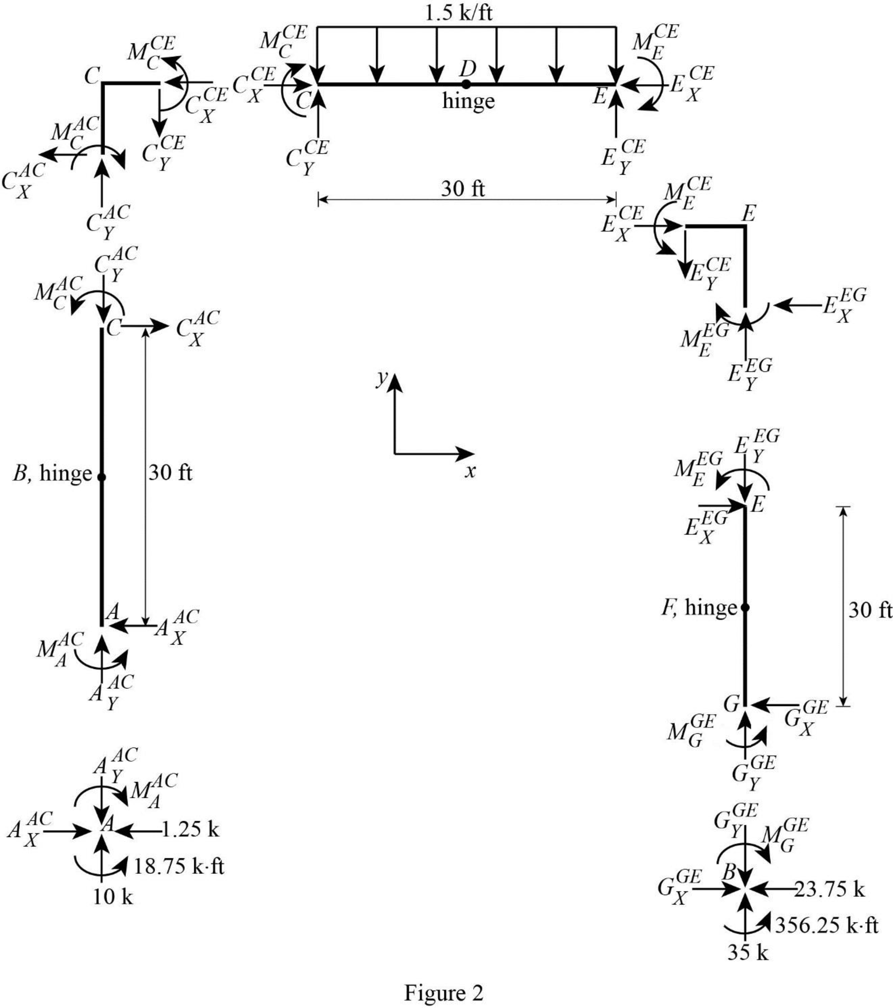
Consider point A:
Resolve the vertical component of forces.
Resolve the horizontal component of forces.
Take moment about the point A.
Consider the member AC:
Resolve the vertical component of forces.
Resolve the horizontal component of forces.
Take moment about the point C.
Consider the point C:
Resolve the vertical component of forces.
Resolve the horizontal component of forces.
Take moment about the point C.
Consider the member CDE:
Resolve the vertical component of forces.
Resolve the horizontal component of forces.
Take moment about the point E.
Consider the point E:
Resolve the vertical component of forces.
Resolve the horizontal component of forces.
Take moment about the point E.
Consider the point G:
Resolve the vertical component of forces.
Resolve the horizontal component of forces.
Take moment about the point G.
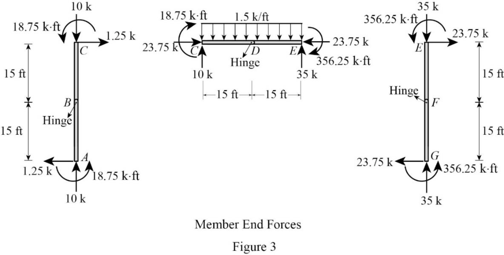
Plot the moment end forces of the frame as in Figure 3.
Refer to the moment end force diagram plot the shear diagram, bending moment diagram, and the axial force diagrams.
Plot the shear force diagram as in Figure 4.
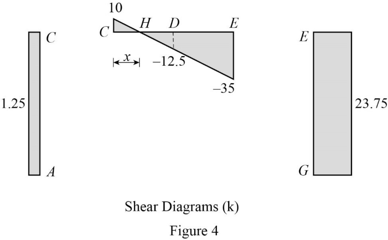
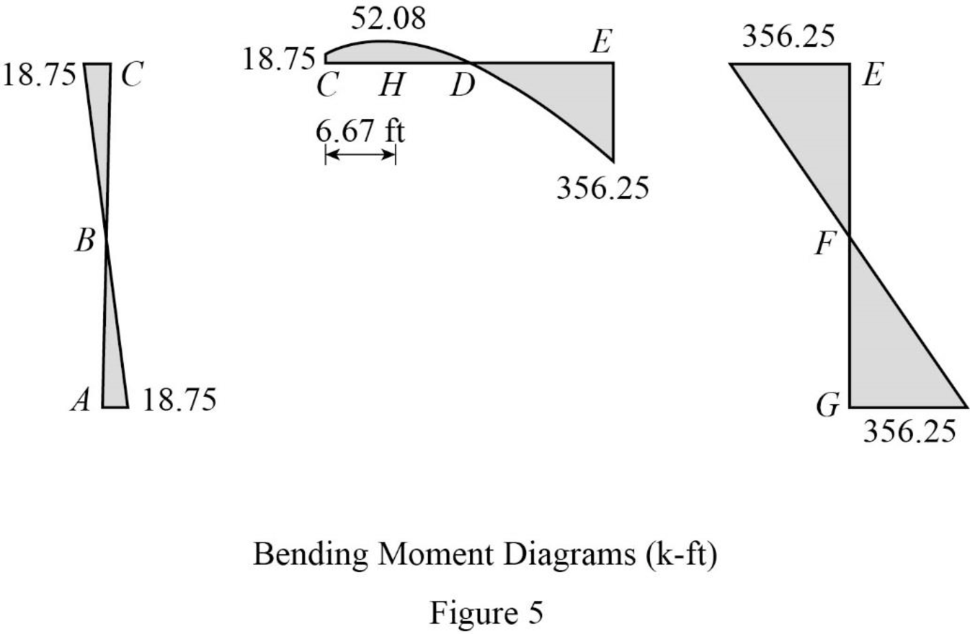
Refer to the shear force diagram, the maximum bending moment occurs at point F where the shear force changes sign.
Use similar triangle concept for the region CE:
Plot the bending moment diagram as in Figure 5.
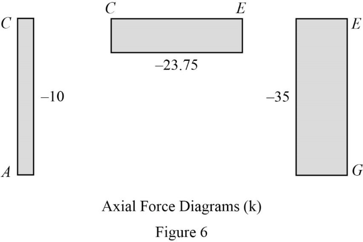
Plot the axial force diagram as in Figure 6.
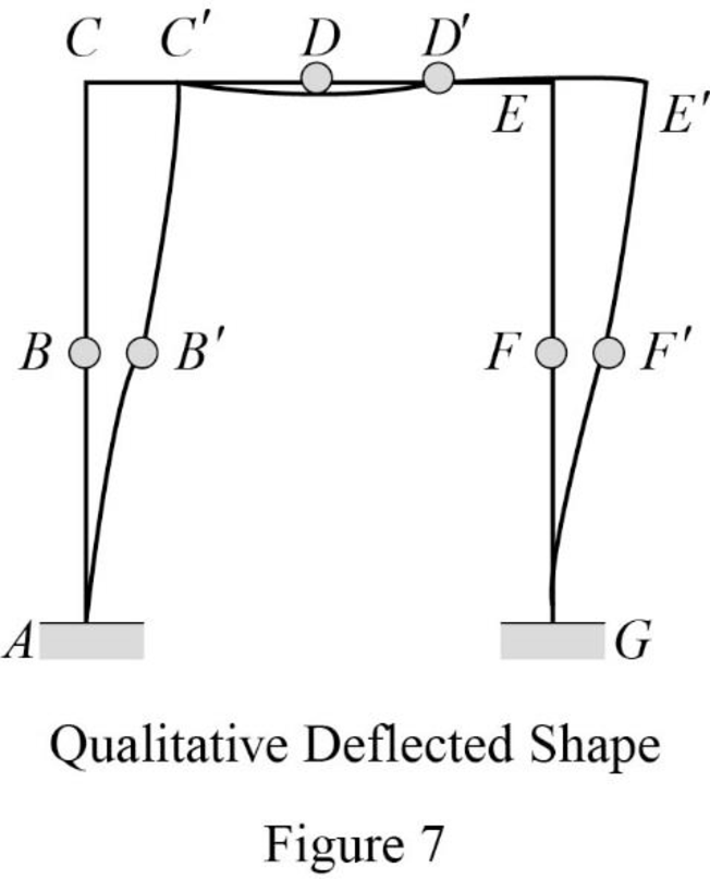
Plot the qualitative deflected shape as in Figure 7.
Want to see more full solutions like this?
Chapter 5 Solutions
STRUCTURAL ANALYSIS (LL)


- For the following Frames: Sketch the deflected shape Draw shear and moment diagram and indicate key values Determine the shear and moment in the frames as a function of x. 15 kN/m 20 kN 5 m 10 kN 4 m 2 m A 5 kN 5 kN В 4 m 3 kN/m- 500 N/m -3 m 4 m -3 m 3m 3 m 95kN 15 kN/m D 5 m 10 m 10 kN/m B 12 m 5 marrow_forwardQ. I Determine the slope at the supports of the beam shown in Fig. I using the moment-area method. Also, determine the deflections at B. E = 29,000 ksi and I = 1,000 in.*. 40 k 60 k Fig. 1 B 10 ft 1 10 ft 21 10 f 1arrow_forwardFor the shown frame: 1. Calculate support reactions. 2. Draw B.M.D., S.F.D. and N.F.D. 3. Use the Virtual Work Method to calculate: (a) Horizontal deflection of Point H, (b) Right side rotation of Point F, due to the given loads. El is 15x105 kip.ft2. Axial deformations are negligible. 20 kip | 3 kip/ft A D H 5 ft 50 kip.... 5 ft 6 ft 15 ft E A 4 ft 30 kip 7.5 ft F 7.5 ft 7.5 ft G B Tim 6 ft ..... 40 kip N 6 ft 8 ftarrow_forward
- The truss shown in Fig.3 is supported by a roller at C and a hinge at D. Use Castigliano's theorem to calculate the horizontal deflection for point B. E-200 B. kN/mm² and A-800 mm² for all members. s) 15 kN 2 m 20 KN B Th 2 m Fig.3arrow_forwardQ. 3 Determine the deflections at B and C for the beam shown in Fig. 2 using the conjugate beam method. Also, determine the slope at D. El is constant. E = 20,000ksi and I = 31500 in.¹. 1.5 k/ft H -6 ft 30 k B +4ft- C -5 ft- Fig. 2arrow_forwardHelp me solve the question in the imagearrow_forward
- Q. 2 Determine the deflections at B and C for the beam shown in Fig. 2 using the moment- area method. Also, determine the slope at D. EI is constant. E = 20,000 ksi and I = 31500 in.4. 1.5 k/ft 30 k Fig. 2 A В 6 ft 4 ft- 5 ftarrow_forward4- Determine the vertical and horizontal deflections at joint B of the truss shown using the virtual work method. 3 m m 100 kN -50 kN m EA constant E = 70 GPa A = 1,000 mm²arrow_forwardDetermine the slopes and deflections at points B and C of the cantilever beam shown in Fig. 6.14(a) by the conjugate beam methodarrow_forward
- 7.34 Use the graphical method to construct the shear-force and bending-moment diagrams for the beam shown. Label all significant points on each diagram and identify the maximum moments along with their respective locations. Additionally: (a) Determine V and M in the beam at a point located 0.75 m to the right of B. (b) Determine V and M in the beam at a point 15 kN 18 kN 40 kN/m 3 m 6 m 4 m located 1.25 m to the left of C. Fig. P7.34arrow_forwardQuestion 3 Consider the two forces F en F2 acting on the post in Hibbeler (edition 14) Problem 2.134 p 80. 3.1 Determine the angle 0. F, = 400 N 3.2 Determine (a) the projection of F, on the line of action of F2 and (b) the correspon- ding component related to the projection. Express your answers in cartesian vector form. 35° 120° y Note: The projection of F1 on the line of action F2 is parallel to F2, and most likely not equal to F2. 60° 20° 45 3.3 Determine the projection of F2 on the line of action of F1 as well as the correspon- ding component. Express your answers in cartesian vector form. F; = 400 Narrow_forwardDetermine the magnitudes of the projection of the force F shown onto the u and υ axes.arrow_forward
