Statics and Mechanics of Materials (5th Edition)
5th Edition
ISBN: 9780134382869
Author: HIBBELER
Publisher: PEARSON
expand_more
expand_more
format_list_bulleted
Videos
Textbook Question
Chapter 5, Problem 8RP
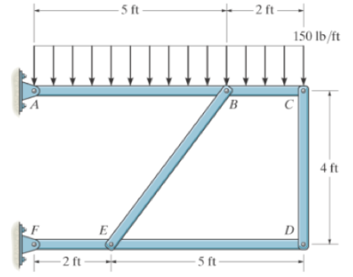
Determine the resultant forces at pins B and C on member ABC of the four-member frame.
Prob. R6-8
Expert Solution & Answer
Want to see the full answer?
Check out a sample textbook solution
Students have asked these similar questions
Determine the resultant force at pins A, B, and C on the three-member frame. Given: F = 40N, w = 10, L = 1.
The Engine Part has a weight of 400 N. Find components of this force (which is acting downward at point B) along members BA and BC
Draw the Free-Body Diagram if the weight acts on point G
Chapter 5 Solutions
Statics and Mechanics of Materials (5th Edition)
Ch. 5.3 - In each ease, calculate the support reactions and...Ch. 5.3 - Identify the zero-force members in each truss....Ch. 5.3 - Determine the force in each member of the truss...Ch. 5.3 - Determine the force in each member of the truss...Ch. 5.3 - Determine the force in each member of the truss...Ch. 5.3 - Determine the greatest load P that can be applied...Ch. 5.3 - Identify the zero-force members in the truss....Ch. 5.3 - Determine the force in each member of the truss...Ch. 5.3 - Determine the force in each member of the truss...Ch. 5.3 - Determine the force in each member of the truss...
Ch. 5.3 - Determine the force in each member of the truss...Ch. 5.3 - Determine the force in each member of the truss...Ch. 5.3 - Determine the force in each member of the truss,...Ch. 5.3 - Determine the force in each member of the truss,...Ch. 5.3 - Determine the force in each member of the truss...Ch. 5.3 - Determine the force in each member of the truss in...Ch. 5.3 - Members AB and BC can each support a maximum...Ch. 5.3 - Members AB and BC can each support a maximum...Ch. 5.3 - Determine the force in each member of the truss...Ch. 5.3 - If the maximum force that any member can support...Ch. 5.3 - Determine the force in each member of the truss...Ch. 5.3 - Determine the force in each member of the truss...Ch. 5.3 - Determine the force in each member of the truss...Ch. 5.3 - Determine the force in each member of the truss...Ch. 5.4 - Determine the force in members BC, CF, and FE and...Ch. 5.4 - Determine the force in members LK, KC, and CD of...Ch. 5.4 - Determine the force in members KJ, KD, and CD of...Ch. 5.4 - Determine the force in members EF, CF, and BC of...Ch. 5.4 - Determine the force in members GF, GD, and CD of...Ch. 5.4 - Determine the force in members DC, HI, and JI of...Ch. 5.4 - Determine the force in members DC, HC and HI of...Ch. 5.4 - Determine the force in members ED, EH, and GH of...Ch. 5.4 - Determine the force in members HG, HE, and DE of...Ch. 5.4 - Determine the force in members CD, HI, and CH of...Ch. 5.4 - Determine the force in members CD, CJ, KJ, and DJ...Ch. 5.4 - Prob. 22PCh. 5.4 - The Howe truss is subjected to the loading shown....Ch. 5.4 - The Howe truss is subjected to the loading shown....Ch. 5.4 - Determine the force in members EF, CF, and BC, and...Ch. 5.4 - Determine the force in members AF, BF, and BC, and...Ch. 5.4 - Prob. 27PCh. 5.4 - Determine the force in members BC, BE, and EF of...Ch. 5.4 - Prob. 29PCh. 5.4 - Determine the force in members CD, CF, and CG and...Ch. 5.4 - Determine the force developed in members FE, EB,...Ch. 5.5 - In each ease, identify any two-force members, and...Ch. 5.5 - F5-13. Determine the force P needed to hold the...Ch. 5.5 - Determine the horizontal and vertical components...Ch. 5.5 - If a 100-N force is applied to the handles of the...Ch. 5.5 - Determine the horizontal and vertical components...Ch. 5.5 - Determine the force P required to hold the 100-lb...Ch. 5.5 - In each case, determine the force P required to...Ch. 5.5 - Determine the force P required to hold the 50-kg...Ch. 5.5 - Determine the force P required to hold the 150-kg...Ch. 5.5 - Determine the reactions at the supports A, C, and...Ch. 5.5 - Determine the resultant force at pins A, B, and C...Ch. 5.5 - Determine the reactions at the supports at A, E,...Ch. 5.5 - The wall crane supports a load of 700 lb....Ch. 5.5 - The wall crane supports a load of 700 lb....Ch. 5.5 - Determine the horizontal and vertical components...Ch. 5.5 - Determine the force in members FD and DB of the...Ch. 5.5 - Determine the force that the smooth 20-kg cylinder...Ch. 5.5 - The three power lines exert the forces shown on...Ch. 5.5 - The pumping unit is used to recover oil. When the...Ch. 5.5 - Determine the force that the jaws J of the metal...Ch. 5.5 - Prob. 47PCh. 5.5 - Prob. 48PCh. 5.5 - Prob. 49PCh. 5.5 - Determine the force created in the hydraulic...Ch. 5.5 - The hydraulic crane is used to lift the 1400-lb...Ch. 5.5 - Determine force P on the cable if the spring is...Ch. 5.5 - Prob. 53PCh. 5.5 - Prob. 54PCh. 5.5 - Prob. 55PCh. 5.5 - Determine the force P on the cable if the spring...Ch. 5.5 - Prob. 57PCh. 5.5 - Prob. 58PCh. 5.5 - Prob. 59PCh. 5.5 - Prob. 60PCh. 5.5 - The platform scale consists of a combination of...Ch. 5 - All the problems solutions must include FBDs....Ch. 5 - Determine the force in each member of the truss...Ch. 5 - Determine the force in member GJ and GC of the...Ch. 5 - Determine the force in members GF, FB, and BC of...Ch. 5 - Prob. 5RPCh. 5 - Determine the horizontal and vertical components...Ch. 5 - Prob. 7RPCh. 5 - Determine the resultant forces at pins B and C on...
Knowledge Booster


Learn more about
Need a deep-dive on the concept behind this application? Look no further. Learn more about this topic, mechanical-engineering and related others by exploring similar questions and additional content below.Similar questions
- The mobile crane is symmetrically supported by two outriggers at A and B to relieve the suspension of the vehicle on which it sits and to provide extra stability. Determine the vertical reactions at each of the two outriggers as a function of boom angle when the boom is carrying a 1.2 Mg load and the crane and truck have a combined mass of 18 Mg and the boom has a mass of 2 Mg. 0 = 45°arrow_forwardThe three A-36 steel wires each have a diameter of 2 mm and unloaded lengths of LAC = 1.60 m and LAB = LAD = 2.00 m. Determine the force in each wire after the 150-kg mass is suspended from the ring at A.arrow_forwardDetermine the magnitude of the pin force at A.Assume W = 665 lb, a = 3.7 ft, b = 2.9 ft, r = 8 in.arrow_forward
- Find the minimum force P required for impending motion of the block up the inclined surface, given: Mblock = 65 kg, θ = 52 °, μ = 0.4arrow_forwardUsing Method Of Sections, Determine The Forces In Members CD And DF. 5 KN 4 KN 3 KN 2 KN |-3 M +-3m-+-3 M+-3m- 3.arrow_forwardDetermine the forces acting on each of the member of the structurearrow_forward
- Determine the n- and t-components of the force F which is exerted by the rod AB on the crank OA. Evaluate your general expression for F = 95 N and (a) θ = 16°, β = 9° and (b) θ = 22°, β = 30°arrow_forwardThe ramp is used as passengers board a small commuter airplane. The total mass of the ramp and six passengers is 730 kg with a mass center at G. Determine the force in the hydraulic cylinder AB (positive if in tension, negative if in compression) and the magnitude of the pin reaction at C.arrow_forwardFind the tension in cable BE that supports the bar ABCD described in Prob. 5.6.arrow_forward
- the man has a mass of 85.00 kg and stands at the center of the plank with a weight 150.00 N. if the planes A and B are smooth, determine the reactions and tension in the cord when angle alpha=48.00° and angle theta=23.00°arrow_forwardThe plate is made of steel having a density of 7850kg/m3. If the thickness of the plate is 10 mm,determine the horizontal and vertical components ofreaction at the pin A and the tension in cable BC.arrow_forwardDraw the free-body diagram of the uniform bar, which has a mass of 100 kg and a center of mass at G. The supports A, B, and C are smooth.arrow_forward
arrow_back_ios
SEE MORE QUESTIONS
arrow_forward_ios
Recommended textbooks for you
 International Edition---engineering Mechanics: St...Mechanical EngineeringISBN:9781305501607Author:Andrew Pytel And Jaan KiusalaasPublisher:CENGAGE L
International Edition---engineering Mechanics: St...
Mechanical Engineering
ISBN:9781305501607
Author:Andrew Pytel And Jaan Kiusalaas
Publisher:CENGAGE L
Physics 33 - Fluid Statics (1 of 10) Pressure in a Fluid; Author: Michel van Biezen;https://www.youtube.com/watch?v=mzjlAla3H1Q;License: Standard YouTube License, CC-BY