Mastering Engineering with Pearson eText -- Standalone Access Card -- for Statics and Mechanics of Materials
5th Edition
ISBN: 9780134395104
Author: HIBBELER
Publisher: PEARSON
expand_more
expand_more
format_list_bulleted
Videos
Textbook Question
Chapter 5.5, Problem 45P
The pumping unit is used to recover oil. When the walking beam ABC is horizontal, the force acting in the wireline at the well head is 250 lb, Determine the torque M which must be exerted by the motor in order to overcome this load. The horse-head C weighs 60 lb and has a center of gravity at GC. The walking beam ABC has a weight of 130 lb and a center of gravity at GB, and the counterweight has a weight of 200 lb and a center of gravity at GW. The pitman, AD, is pin connected at its ends and has negligible weight.
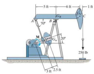
Prob. 5-45
Expert Solution & Answer

Trending nowThis is a popular solution!

Students have asked these similar questions
The pumping unit is used to recover oil. When the walking beam ABC is horizontal, the forceacting in the wireline at the well head is 250 lb. Determine the torque M which must beexerted by the motor in order to overcome this load. The horse-head C weighs 60 lb andhas a center of gravity at Gc. The walking beam ABC has a weight of 130 lb and a centerof gravity at GB, and the counterweight has a weight of 200 lb and a center of gravity atGW. The pitman, AD, is pin connected at its ends and has negligible weight.
The cylinder has a mass of 30 kg and is mounted on an axle that is supported by bearings at A and B. If the axle is turning at 40 rad/s (direction see figure) determine the vertical components of force acting at the bearings at this instant
Determine the magnitude of the pin force at A.Assume W = 665 lb, a = 3.7 ft, b = 2.9 ft, r = 8 in.
Chapter 5 Solutions
Mastering Engineering with Pearson eText -- Standalone Access Card -- for Statics and Mechanics of Materials
Ch. 5.3 - In each ease, calculate the support reactions and...Ch. 5.3 - Identify the zero-force members in each truss....Ch. 5.3 - Determine the force in each member of the truss...Ch. 5.3 - Determine the force in each member of the truss...Ch. 5.3 - Determine the force in each member of the truss...Ch. 5.3 - Determine the greatest load P that can be applied...Ch. 5.3 - Identify the zero-force members in the truss....Ch. 5.3 - Determine the force in each member of the truss...Ch. 5.3 - Determine the force in each member of the truss...Ch. 5.3 - Determine the force in each member of the truss...
Ch. 5.3 - Determine the force in each member of the truss...Ch. 5.3 - Determine the force in each member of the truss...Ch. 5.3 - Determine the force in each member of the truss,...Ch. 5.3 - Determine the force in each member of the truss,...Ch. 5.3 - Determine the force in each member of the truss...Ch. 5.3 - Determine the force in each member of the truss in...Ch. 5.3 - Members AB and BC can each support a maximum...Ch. 5.3 - Members AB and BC can each support a maximum...Ch. 5.3 - Determine the force in each member of the truss...Ch. 5.3 - If the maximum force that any member can support...Ch. 5.3 - Determine the force in each member of the truss...Ch. 5.3 - Determine the force in each member of the truss...Ch. 5.3 - Determine the force in each member of the truss...Ch. 5.3 - Determine the force in each member of the truss...Ch. 5.4 - Determine the force in members BC, CF, and FE and...Ch. 5.4 - Determine the force in members LK, KC, and CD of...Ch. 5.4 - Determine the force in members KJ, KD, and CD of...Ch. 5.4 - Determine the force in members EF, CF, and BC of...Ch. 5.4 - Determine the force in members GF, GD, and CD of...Ch. 5.4 - Determine the force in members DC, HI, and JI of...Ch. 5.4 - Determine the force in members DC, HC and HI of...Ch. 5.4 - Determine the force in members ED, EH, and GH of...Ch. 5.4 - Determine the force in members HG, HE, and DE of...Ch. 5.4 - Determine the force in members CD, HI, and CH of...Ch. 5.4 - Determine the force in members CD, CJ, KJ, and DJ...Ch. 5.4 - Prob. 22PCh. 5.4 - The Howe truss is subjected to the loading shown....Ch. 5.4 - The Howe truss is subjected to the loading shown....Ch. 5.4 - Determine the force in members EF, CF, and BC, and...Ch. 5.4 - Determine the force in members AF, BF, and BC, and...Ch. 5.4 - Prob. 27PCh. 5.4 - Determine the force in members BC, BE, and EF of...Ch. 5.4 - Prob. 29PCh. 5.4 - Determine the force in members CD, CF, and CG and...Ch. 5.4 - Determine the force developed in members FE, EB,...Ch. 5.5 - In each ease, identify any two-force members, and...Ch. 5.5 - F5-13. Determine the force P needed to hold the...Ch. 5.5 - Determine the horizontal and vertical components...Ch. 5.5 - If a 100-N force is applied to the handles of the...Ch. 5.5 - Determine the horizontal and vertical components...Ch. 5.5 - Determine the force P required to hold the 100-lb...Ch. 5.5 - In each case, determine the force P required to...Ch. 5.5 - Determine the force P required to hold the 50-kg...Ch. 5.5 - Determine the force P required to hold the 150-kg...Ch. 5.5 - Determine the reactions at the supports A, C, and...Ch. 5.5 - Determine the resultant force at pins A, B, and C...Ch. 5.5 - Determine the reactions at the supports at A, E,...Ch. 5.5 - The wall crane supports a load of 700 lb....Ch. 5.5 - The wall crane supports a load of 700 lb....Ch. 5.5 - Determine the horizontal and vertical components...Ch. 5.5 - Determine the force in members FD and DB of the...Ch. 5.5 - Determine the force that the smooth 20-kg cylinder...Ch. 5.5 - The three power lines exert the forces shown on...Ch. 5.5 - The pumping unit is used to recover oil. When the...Ch. 5.5 - Determine the force that the jaws J of the metal...Ch. 5.5 - Prob. 47PCh. 5.5 - Prob. 48PCh. 5.5 - Prob. 49PCh. 5.5 - Determine the force created in the hydraulic...Ch. 5.5 - The hydraulic crane is used to lift the 1400-lb...Ch. 5.5 - Determine force P on the cable if the spring is...Ch. 5.5 - Prob. 53PCh. 5.5 - Prob. 54PCh. 5.5 - Prob. 55PCh. 5.5 - Determine the force P on the cable if the spring...Ch. 5.5 - Prob. 57PCh. 5.5 - Prob. 58PCh. 5.5 - Prob. 59PCh. 5.5 - Prob. 60PCh. 5.5 - The platform scale consists of a combination of...Ch. 5 - All the problems solutions must include FBDs....Ch. 5 - Determine the force in each member of the truss...Ch. 5 - Determine the force in member GJ and GC of the...Ch. 5 - Determine the force in members GF, FB, and BC of...Ch. 5 - Prob. 5RPCh. 5 - Determine the horizontal and vertical components...Ch. 5 - Prob. 7RPCh. 5 - Determine the resultant forces at pins B and C on...
Knowledge Booster


Learn more about
Need a deep-dive on the concept behind this application? Look no further. Learn more about this topic, mechanical-engineering and related others by exploring similar questions and additional content below.Similar questions
- The three bars are welded together to form a rigid unit that is supported by three slider bearings. Neglecting the weights of the bars, determine the magnitudes of the three bearing reactions caused by the 120-lbin. couple.arrow_forwardThe homogeneous bar AB weighs 25 lb. Determine the magnitudes of the forces acting on the bar at A and B. Neglect friction.arrow_forwardThe mass center G of the 1300-kg rear-engine car is located as shown in the figure. Determine the normal force under each tire when the car is in equilibrium. State any assumptions.arrow_forward
- Both pulleys are fixed to the shaft and as the shaft turns with constant angular velocity, the power of pulley A is transmitted to pulley B. Determine the horizontal tension T in the belt on pulley B and the x, y, z components ofreaction at the journal bearing C and thrust bearing D if θ = 0°. The bearings are in proper alignment and exert only force reactions on the shaft.arrow_forwardBeam has a mass of 75.0 kg. F1 = 85.0 N F2 = 150.0 N F3 = 125.0 N a) Locate the center of gravity of the beam. Determine b) the net torque on thebeam about point O; c) the required magnitude of F3 to keep the beamstationaryarrow_forwardThe smooth disks D and E have a weight of 220 lb and 100 lb, respectively. If a horizontal force of P = 220 lb is applied to the center of disk E, determine the normal reactions at the points of contact with the ground at A, B, and C.arrow_forward
- The jib crane is designed for a maximum capacity of 7 kN, and its uniform I-beam has a mass of 240 kg. Plot the magnitude R of the force on the pin at A as a function of x through its operating range of x = 0.2 m to x = 3.7 m. On the same set of axes, plot the x- and y-components of the pin reaction at A. Do these plots on a separate piece of paper. Then answer the following questions in Wiley Plus as a check for your work.(a) What is the value of R when x = 1.9 m?(b) What is the value of R when x = 3.2 m?(c) Determine the minimum value of R and the corresponding value of x.(d) For what value of R should the pin at A be designed?arrow_forwardA 300kg counterweight with center of mass at G is mounted on the AB crank rod of the oil pump unit. If the motor supplies a torque M = 250Nm determine the force F developed by the fixed cable attached to the end of the mobile beam DEFarrow_forwardDraw the free-body diagram of the uniform bar, which has a mass of 100 kg and a center of mass at G. The supports A, B, and C are smooth.arrow_forward
- The Engine Part has a weight of 400 N. Find components of this force (which is acting downward at point B) along members BA and BCarrow_forwardThe wheelbarrow has a mass of 75 kg, determine the vertical force the mas should exert to tilt the wheelbarrow and the contact force at point A of the horizontal smooth surface. Fv= NA =arrow_forwardThe jib crane is designed for a maximum capacity of 14 kN, and its uniform I-beam has a mass of 270 kg. Plot the magnitude R of the force on the pin at A as a function of x through its operating range of x = 0.2 m to x = 4.0 m. On the same set of axes, plot the x- and y-components of the pin reaction at A. Do these plots on a separate piece of paper. Then answer the following questions in Wiley Plus as a check for your work. (You can disregard the plot, I only need a, b, c, and d)arrow_forward
arrow_back_ios
SEE MORE QUESTIONS
arrow_forward_ios
Recommended textbooks for you
 International Edition---engineering Mechanics: St...Mechanical EngineeringISBN:9781305501607Author:Andrew Pytel And Jaan KiusalaasPublisher:CENGAGE L
International Edition---engineering Mechanics: St...
Mechanical Engineering
ISBN:9781305501607
Author:Andrew Pytel And Jaan Kiusalaas
Publisher:CENGAGE L
Mechanical SPRING DESIGN Strategy and Restrictions in Under 15 Minutes!; Author: Less Boring Lectures;https://www.youtube.com/watch?v=dsWQrzfQt3s;License: Standard Youtube License