
Principles Of Electric Circuits
10th Edition
ISBN: 9780134879482
Author: Floyd, Thomas L.
Publisher: Pearson,
expand_more
expand_more
format_list_bulleted
Concept explainers
Videos
Textbook Question
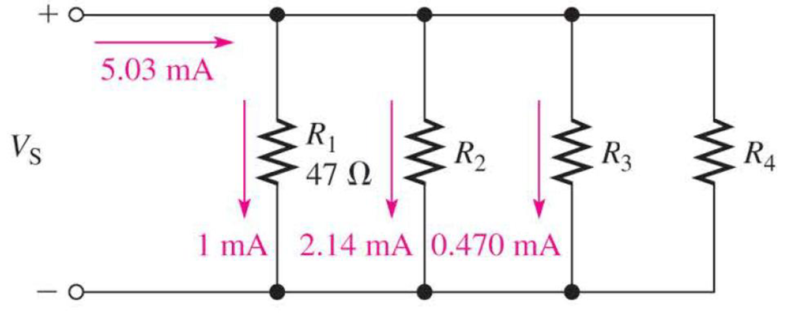
Chapter 6, Problem 11P
In the circuit of Figure 6-65, determine the resistance R2, R3, and R4.
Figure 6-65
Expert Solution & Answer
Want to see the full answer?
Check out a sample textbook solution
Students have asked these similar questions
Determine the value of a load resistor connected between terminals A and B in Figure 6-82 for maximum power transfer to the load resistor.
Determine the value of Rx in the balanced bridge in Figure 6-80.
In Figure 6-85 , use the superposition theorem to find the current in R3 and what is the current through R2 ?
Chapter 6 Solutions
Principles Of Electric Circuits
Ch. 6 - Five resistors are positioned on a protoboard as...Ch. 6 - How would you connect all of the resistors in...Ch. 6 - If a third branch is added to the circuit in...Ch. 6 - Determine IT and I2 if a fourth branch is added to...Ch. 6 - How much current will an ammeter measure when it...Ch. 6 - When the brake lights are applied, the total...Ch. 6 - If a 33 resistor is connected in parallel in...Ch. 6 - Calculate the total resistance connected to the...Ch. 6 - If two of the speakers are removed, what is the...Ch. 6 - The basic circuit for a rear window defroster can...
Ch. 6 - If you need to obtain a total resistance of 130 ,...Ch. 6 - Sometimes a direct measurement of resistance is...Ch. 6 - Determine the current through RL in Figure 6-0...Ch. 6 - Figure 6-35 Determine the current through each...Ch. 6 - Determine the total amount of power in the...Ch. 6 - The amplifier in one channel of a stereo system as...Ch. 6 - In Figure 6-51, there is a total current of 31.09...Ch. 6 - Your ohmmeter indicates 9.6 k between pin 2 and...Ch. 6 - A 330 resistor, a 270 resistor, and a 68 ...Ch. 6 - Refer to Figure 6-83 If R7 opens, the resistance...Ch. 6 - Determine whether or not all the resistors in...Ch. 6 - The following currents are measured in the same...Ch. 6 - There is a total of 500 mA of current into five...Ch. 6 - In the circuit of Figure 6-65, determine the...Ch. 6 - The electrical circuit in a room has a ceiling...Ch. 6 - The following resistors are connected in parallel:...Ch. 6 - What is the total current in each circuit of...Ch. 6 - Find the values of the unspecified quantities...Ch. 6 - What is the current through each resistor in...Ch. 6 - Determine all of the resistor values in Figure...
Knowledge Booster


Learn more about
Need a deep-dive on the concept behind this application? Look no further. Learn more about this topic, electrical-engineering and related others by exploring similar questions and additional content below.Similar questions
- Determine the resistance values using the color code and calculate all missing values in Figure 6-26. FIGURE 6-26 Determine resistor values using the color and find all missing electrical values.arrow_forwardRefer to the circuit shown in Figure 6-22. The circuit has an applied voltage of 24 V and the resistors have values as follows: R1=1kR2=300R3=750R4=1k An ammeter and a voltmeter indicate the following values: IT=42.5mAI1=24mAE1=24VI2=18.5mAE2=5.5VI3=0AE3=18.5VI4=18.5mAE4=18.5V What is the most likely problem with this circuit? FIGURE 8-22 Determine resistor values using the color code and find all missing electrical values.arrow_forwardA voltage divider consists of a 3,000 - Ω, a 5,000 - Ω, and 10,000 – Ω resistor in series. The series current is 15 mA. Find the following:(a) the voltage drop across each resistance(b) the total voltage(c) the total resistance; and (d) power in each resistorarrow_forward
- I have been given this circuit and I had to find the total current by using the current divider law. Can you tell me if my problem solving is correct? I haven't been given the right answer.arrow_forwardA voltage divider consists of a 3,000 - Ω, a 5,000 - Ω, and 10,000 – Ω resistor in series. The series current is 15 mA. Illustrate the circuit diagram and find (a) the voltage drop across each resistance, (b) the total voltage, (c) the total resistance and (d) power in each resistor.arrow_forwardWhen two resistors A and B are connected in series, the total resistance is 32ohms. When connected in parallel, the total resistance is 7.5ohms. Determine the possible value of A.arrow_forward
- Subject: Circuit Isolution please Three resistors of 8.4Ω,6.8Ω, and 4.8Ωare connected in series across a 100V source. What is the voltage across the 6.8Ω resistor?arrow_forwardwhen two resistors A and B are connected in series, the total resistance is 36 ohms. when connected in parallel, the total resistance is 8 ohms. what is the ratio of the resistance Ra to resistance Rb . assume Raarrow_forwardCan anyone help with number 4-6arrow_forward
- a resistance of 6 ohms is connected in parallel with a 3 ohms resistor. both resistances are then connected in series with an 8 ohms resistor through a 6 ohms resistor.arrow_forwardWhen two resistors A and B are connected in series, the total resistance is 36 ohms. When connected in parallel, the total resistance is 8 ohms. What is the ratio of the resistance RA to resistance Rg. Assume RA <Rp.arrow_forwardThe circuit is composed of series parallel resistors with a voltage source. Compute for total resistance (Rt) , Total current (It) and V1…..when SW1 is open.arrow_forward
arrow_back_ios
SEE MORE QUESTIONS
arrow_forward_ios
Recommended textbooks for you
 Delmar's Standard Textbook Of ElectricityElectrical EngineeringISBN:9781337900348Author:Stephen L. HermanPublisher:Cengage Learning
Delmar's Standard Textbook Of Electricity
Electrical Engineering
ISBN:9781337900348
Author:Stephen L. Herman
Publisher:Cengage Learning
What is an electric furnace and how does it work?; Author: Fire & Ice Heating and Air Conditioning Inc;https://www.youtube.com/watch?v=wjAWecPGi0M;License: Standard Youtube License