
Introductory Circuit Analysis
13th Edition
ISBN: 9780133923919
Author: Boylestad, Robert L.
Publisher: Pearson Education
expand_more
expand_more
format_list_bulleted
Concept explainers
Videos
Textbook Question
thumb_up100%
Chapter 6, Problem 12P
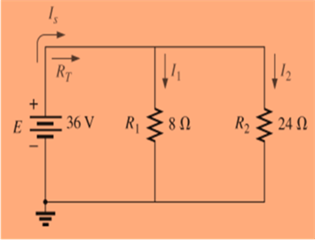
For the parallel network in Fig. 6.75:
- Find the total resistance.
- What is the voltage across each branch?
- Determine the source current and the current through each branch.
- Verify that the source current equals the sum of the branch currents.
Expert Solution & Answer
Want to see the full answer?
Check out a sample textbook solution
Students have asked these similar questions
Find the unknown quantities for the networks in fig.6.93 using the information provided
Refer to Fig. 6-6. Do not correct for VBE.Assume that β = 80. Determine VCE.
6. Need help for our practice problem
Chapter 6 Solutions
Introductory Circuit Analysis
Ch. 6 - For each configuration in Fig. 6.64, find the...Ch. 6 - For each configuration of Fig. 6.65, �nd the...Ch. 6 - For the network in Fig. 6.66: Find the elements...Ch. 6 - Find the total resistance for each configuration...Ch. 6 - Find the total resistance for each configuration...Ch. 6 - For each circuit board in Fig. 6.69, �nd the...Ch. 6 - The total resistance of each of the configurations...Ch. 6 - The total resistance for each configuration of...Ch. 6 - For the parallel network in Fig. 6.72, composed of...Ch. 6 - What is the ohmmeter reading for each...
Ch. 6 - Determine R1 for the network in Fig. 6.749.Ch. 6 - For the parallel network in Fig. 6.75: Find the...Ch. 6 - For the network of Fig. 6.76: Find the current...Ch. 6 - Repeat the analysis of Problem 13 for the network...Ch. 6 - For the parallel network in Fig. 6.78: Without...Ch. 6 - Given the information provided in Fig. 6.79, find:...Ch. 6 - Use the information in Fig. 6.80, to calculate:...Ch. 6 - Given the information provided in Fig. 6.81, find...Ch. 6 - For the network of Fig. 6.82, find: The voltage V....Ch. 6 - Using the information provided in Fig. 6.83 find:...Ch. 6 - For the network in Fig. 6.77: Redraw the network...Ch. 6 - For the configuration in Fig. 6.84: Find the total...Ch. 6 - Eight holiday lights are connected in parallel as...Ch. 6 - Determine the power delivered by the dc battery in...Ch. 6 - A portion of a residential service to a home is...Ch. 6 - For the network in Fig. 6.88: Find the current l1....Ch. 6 - Using Kirchhoffs current law, determine the...Ch. 6 - Using Kirchoffs current law, find the unknown...Ch. 6 - Using Kirchhoffs current law, determine the...Ch. 6 - Using the information provided in Fig. 6.92, find...Ch. 6 - Find the unknown quantities for the networks in...Ch. 6 - Find the unknown quantities for the networks of...Ch. 6 - Based solely on the resistor values, determine all...Ch. 6 - Determine one of the unknown currents of Fig....Ch. 6 - For each network of Fig. 6.97, determine the...Ch. 6 - Parts (a) through (e) of this problem should be...Ch. 6 - Find the unknown quantities for the networks in...Ch. 6 - Find resistance R for the network in Fig. 6.100...Ch. 6 - Design the network in Fig. 6.101 such that I2=2I1...Ch. 6 - Assuming identical supplies in Fig. 6.102: Find...Ch. 6 - Assuming identical supplies, determine currents...Ch. 6 - Assuming identical supplies, determine the current...Ch. 6 - For the simple series con�guration in Fig....Ch. 6 - Given the configuration in Fig. 6.106: What is the...Ch. 6 - Based on the measurements of Fig. 6.107, determine...Ch. 6 - Referring to Fig. 6.108, find the voltage Vab...Ch. 6 - The voltage Va for the network in Fig. 6.109, is...Ch. 6 - Prob. 48PCh. 6 - Using PSpice or Multisim, determine the solution...Ch. 6 - Using PSpice or Multisim, determine the solution...
Additional Engineering Textbook Solutions
Find more solutions based on key concepts
How many coulombs do 93.8 1016 electrons represent?
Principles Of Electric Circuits
What is the color code for a 365- five-band precision resistor with a tolerance of 5 percent?
ELECTRICITY FOR TRADES (LOOSELEAF)
The voltage source of the circuit shown in Fig. P1.29 is given by s(t)=25cos(4104t45)(V). Obtain an expression ...
Fundamentals of Applied Electromagnetics (7th Edition)
For the “tank” circuit in Fig. 14.79, find the resonant frequency.
Figure 14.79
For Probs. 14.39, 14.71, and 1...
Fundamentals of Electric Circuits
A constant voltage of 10V is applied to a 50H inductance, as shown in Figure P3.51 Figure P3 51 The current in ...
Electrical Engineering: Principles & Applications (7th Edition)
Find I0 and I1 in the circuit in Fig.P2.12.
Basic Engineering Circuit Analysis
Knowledge Booster


Learn more about
Need a deep-dive on the concept behind this application? Look no further. Learn more about this topic, electrical-engineering and related others by exploring similar questions and additional content below.Similar questions
- Determine the current drawn from the source in the given circuit in Fig. 6arrow_forwardUse information in fig .6.80 to calculate A. The source voltage E B.the resistance R2 c the current l1 D.the source current Is E The power supplied by the source F. The power supplied to the resistor R1 and R2 G. Compare the power calculated in part(e) to the sum of the power delivered to all the resistor.arrow_forwardGraph the circuit in the image and choose a suitable tree. Obtain circuit equations by the method of beam currents. Calculate the powers of the elements, show that the total power is equal to zero.arrow_forward
- A battery with EMF of 6V and an internal resistance, r= 0.65 ohms is connected to a load resistance R=58 ohms. Determine its terminal voltage.arrow_forwardPlease solve with hundred percent efficiency Don't use solution which is already on site Write neat and clean by hand solution in the order to get positive feedbackarrow_forward7. The longer the length of the arc, the higher will be the Arc Resistance. Select one: True Falsearrow_forward
- For the network in Fig. 6.88:a. Find the current I1.b. Calculate the power dissipated by the 4 Ω resistor.c. Find the current I2.arrow_forwardFor the ladder network in Fig. 7.93. Determine the voltage divider supply resistors for the configuration. Also determine the required wattage rating for each resistor, and compare their levels.arrow_forwardFor the series configuration in Fig. 5.92, constructed using standard value resistors: a.) Without making a single calculation, which resistive element will have the most voltage across it? Which will have the least? b.) Which resistor will have the most impact on the total resistance and the resulting current? Find the total resistance and the current.arrow_forward
- Theoretically determine the currents in each of the resistors for the circuit, using the current divider technique.arrow_forwardFor each configuration in Fig. 5.85, find the individual (not combinations of) elements (voltages sources and/or resistors) that are in series. If necessary, use the fact that elements in series have the same current. Simply list those that satisfy the conditions for a series relationship.arrow_forwardFind the value of Rv (in ohms) needed for a full-scale reading of 5 V.arrow_forward
arrow_back_ios
SEE MORE QUESTIONS
arrow_forward_ios
Recommended textbooks for you
 Delmar's Standard Textbook Of ElectricityElectrical EngineeringISBN:9781337900348Author:Stephen L. HermanPublisher:Cengage Learning
Delmar's Standard Textbook Of Electricity
Electrical Engineering
ISBN:9781337900348
Author:Stephen L. Herman
Publisher:Cengage Learning
Kirchhoff's Rules of Electrical Circuits; Author: Flipping Physics;https://www.youtube.com/watch?v=d0O-KUKP4nM;License: Standard YouTube License, CC-BY