
Concept explainers
Videos
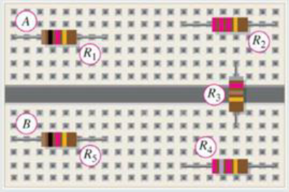
Five resistors are positioned on a protoboard as shown in Figure 6-3. Show the wiring required to connect all of the resistors in parallel between A and B. Draw a schematic and label each of the resistors with its value.
Figure 6-3
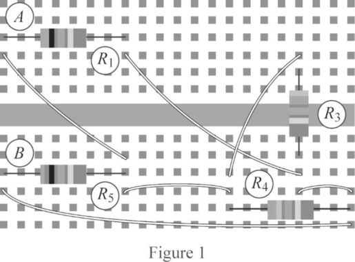
Related Problem How could the circuit wiring be simplified if R2 is removed?
Draw the simplified wiring diagram of the circuit when the resistor
Explanation of Solution
Discussion:
Refer to Figure 6-3 in the textbook for the five resistors in a proto board.
Consider the resistor
The schematic of wiring diagram to connect the resistors
Conclusion:
Thus, the simplified wiring diagram is drawn when
Want to see more full solutions like this?
Chapter 6 Solutions
EBK PRINCIPLES OF ELECTRIC CIRCUITS
Additional Engineering Textbook Solutions
Fundamentals of Applied Electromagnetics (7th Edition)
Electrical Engineering: Principles & Applications (7th Edition)
Introductory Circuit Analysis (13th Edition)
Starting Out with Python (3rd Edition)
C++ How to Program (10th Edition)
Materials for Civil and Construction Engineers (4th Edition)


- why is the total parallel resistance less than the smallest resistancearrow_forwardIn the figure the current in resistance 6 is i6 = 1.50 A and the resistances are R1 = R2 = R3 = 1.53 Ω, R4 = 17.1 Ω, R5 = 8.80 Ω, and R6 = 3.81 Ω. What is the emf of the ideal battery?arrow_forwardThe resistors are connected in series across a 120-V source. The first resistor is 50 Q, the current through the second resistor is 0.5 A, and the voltage drop across the third resistor is 50 V. What are the resistances of the first and third resistors ?arrow_forward
- For given value of the circuit, Vsupply 2002, R6-400 and R7=12002? • What is the voltage drop across R7? 1. 36V b) 48V c) 64V d) 72V 48 Volts 36 Volts 72 Volts = 64 Volts 120 V, and with R₁= 2002, R₂-30.0, R3=750, R4-300, R5= V1 120 V R1 2002 R3 750 R7 >12002 R6 400 R2 2300 R4 >3002 R5 2200arrow_forwardWhat happens to total circuit current when aditional resistance is added in parallel? Current increases. Current remains the same. Current decreases. Current equalizes.arrow_forwardTwo resistors connected in parallel have values of R, - 20 Ohms and R, - 40 Ohms. supply is 10 A. of current through each resistor. 6. The total current coming from the voltage Use the current divider rule to find the value I=10A R200 R = 400 %3Darrow_forward
- In cross circuits, how do i know the resistances are in parallel or in series connection?arrow_forwardAn ammeter is a tool that measures the current (a better name would be V Show Current O Electrons ampmeter) that passes through it. In the circuit simulation you can get Conventional ammeters from the upper right toolbar. Labels Values When current is flowing in through the meter a number value will replace the question mark. Current Votmeter Ammeters Wire Resistivity First make a simple series circuit with a battery, switch, single light bulb and ammeter as shown at right. It's actually not necessary to include the switch but if I left it out then my snapshots would all give away the answers. With the switch closed/current flowing in the circuit, record the current that Current is flowing out of the light bulb and back to the battery. 0.00 A The current is A Now switch the light bulb and the battery so that the ammeter comes before the bulb. Current 0.00 A With the switch closed/current flowing in the circuit, record the current that is flowing out of the battery and into the light…arrow_forwardKindly answer all of the questions please, I will rate you with like/upvote. Please answer all of the questions. Thank you so much.arrow_forward
- B-6-26. Consider the system shown in Figure 6-116. Plot the root loci as a varies from 0 to oo. Determine the value of a such that the damping ratio of the dominant closed-loop poles is 0.5. Figure 6-116 Control system. sta 2 3² (x+2)arrow_forwardA series circuit has resistance values of 160 ohm, 100 ohm, 82 ohm, and 120 ohm. What is the total resistance of this circuit?arrow_forwardCompute total resistance (series-parallel), total current (ohms law), voltage at R1 and R4 (using voltage divider) and current in R4 (using current divider).arrow_forward
 Delmar's Standard Textbook Of ElectricityElectrical EngineeringISBN:9781337900348Author:Stephen L. HermanPublisher:Cengage Learning