
Concept explainers
Videos
(a) For two inductors in series as in Fig. 6.81(a), show that the voltage division principle is
assuming that the initial conditions are zero.
(b) For two inductors in parallel as in Fig. 6.81(b), show that the current-division principle is
assuming that the initial conditions are zero.
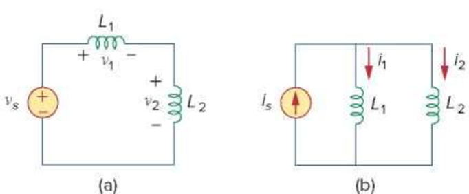
Figure 6.81
For Prob. 6.59.
Want to see the full answer?
Check out a sample textbook solution
Chapter 6 Solutions
FUNDAMENTALS OF ELECTRIC...(LL)>CUSTOM<


- The terminal voltage of a 2-H inductor is v = 10(1 – t ) V. Find the current flowing through it at t = 4s and the energy stored in it at t = 4 s. Assume i(0) = 2 A.arrow_forwardA series RL circuit consisting of a single resistor a single inductor is being supplied by a 20 volt battery. The circuit is currently open and has a initial current of 0 A. The resistor has a resistance value of 100 ahms. If the current flowing through the circuit 1.5 sec after closing the circuit is 0.15 A, find the value of inductancearrow_forward2. Suppose you want a capacitor bank with a total capacitance of 0.750 F and you possess numerous 1.50 mF capacitors. What is the smallest number you could hook together to achieve your goal, and how would you connect them?arrow_forward
- Two coils of inductance 6 H and 8 H are connected in parallel. If their coefficient of coupling is 0.435, calculate the equivalent inductance of the combination if (a) the mutual inductance assists the self-inductance, and (ii) the mutual inductance opposes the self-inductance.arrow_forwardA parallel plate capacitor with 26 interleaved parallel plates having area of cross section,300mm*500mm and plates are separated by 0.030mm using rubber with dielectric constant 8.5.i. Estimate capacitance and charge stored in the capacitor when a voltage, 250V is applied. [3]ii. What are the modifications required to double the charge storing capacity of given capacitorwithout changing the applied voltage? Justify your answer.arrow_forwardA 20.0 μF capacitor, 25.0 μF capacitor, and a 50.0 μF capacitor areconnected in parallel to a 24.0 V battery. a) What is the equivalent capacitance of the combination?b) What is the charge on each capacitor?c) What is the potential difference across each capacitor?d) What is the energy stored in each capacitor?e) What is the total energy stored?arrow_forward
- How can four 100 kΩ resistors be connected so that the equivalent resistance of the four equals 250 kΩ? Sketch the arrangement, describe the resistor arrangement in words, and justify your picture by calculating the equivalent resistance. Repeat this part of the question with four 100 F capacitors and an equivalent capacitance of 75 F.arrow_forwardA 10 pF capacitor is connected in series with a 100 kilo-ohm resistor across a 100 V DC supply.Calculate: (a) the time constant; (b) the initial charging current; (c) the time taken for the p.d. acrossthe capacitor to grow to 63V; (d) the current and the p.d. across the capacitor 3.0 s after it is connectedto the supply; (e) Compare the value obtained in (c) with the time constant of the circuit. What does ittell you about estimating a circuit's time constant?arrow_forwardTwo capacitors 10 and 15 μf are in series with two 20 μf capacitors which are connected in parallel to each other. If the emf supplied is 200 V, find (a) the combined capacitance (b) the charge on the 10 μf and (c) the potential drop across the 15 μf capacitorarrow_forward
- Use realistic inductor values from Appendix H to construct series and parallel combinations of inductors to yield the equivalent inductances specified below. Try to minimize the number of inductors used. Assume that no initial energy is stored in any of the inductors. 1. 8 mH; 2. 45 μH; 3. 180 μH.arrow_forwardThe circuit shown in the attached image contains a voltage source with emf ε = 2.99 V, a resistor with resistance R = 135 kΩ, and a capacitor with capacitance C = 612 nF. When switch S is set to position a, the three circuit elements are in series. When the switch is in position b, the battery is excluded from the circuit. The switch is initially moved to position a, where it remains for a sufficiently long time that the capacitor is fully charged. The switch is now moved to position b. What is the magnitude of the instantaneous current, in amperes, through the resistor the instant the switch makes contact with terminal b? With time meausred the instant that switch S is closed in position b, calculate the time, in seconds, when the charge on the capacitor is one-half of its maximum value. Calculate the current through the resistor, in amperes, at time t = 155.5 ms after the switch is closed in position b.arrow_forward6.35 An inductor has a linear change in current from50 mA to 100 mA in 2 ms and induces a voltage of160 mV. Calculate the value of the inductorarrow_forward
 Introductory Circuit Analysis (13th Edition)Electrical EngineeringISBN:9780133923605Author:Robert L. BoylestadPublisher:PEARSON
 Delmar's Standard Textbook Of ElectricityElectrical EngineeringISBN:9781337900348Author:Stephen L. HermanPublisher:Cengage Learning
 Programmable Logic ControllersElectrical EngineeringISBN:9780073373843Author:Frank D. PetruzellaPublisher:McGraw-Hill Education
 Fundamentals of Electric CircuitsElectrical EngineeringISBN:9780078028229Author:Charles K Alexander, Matthew SadikuPublisher:McGraw-Hill Education
 Electric Circuits. (11th Edition)Electrical EngineeringISBN:9780134746968Author:James W. Nilsson, Susan RiedelPublisher:PEARSON
 Engineering ElectromagneticsElectrical EngineeringISBN:9780078028151Author:Hayt, William H. (william Hart), Jr, BUCK, John A.Publisher:Mcgraw-hill Education,