
Fundamentals of Electric Circuits
6th Edition
ISBN: 9780078028229
Author: Charles K Alexander, Matthew Sadiku
Publisher: McGraw-Hill Education
expand_more
expand_more
format_list_bulleted
Concept explainers
Videos
Textbook Question
Chapter 6, Problem 62P
Consider the circuit in Fig. 6.84. Given that v(t) = 12e−3t mV for t > 0 and i1(0) = −30 mA, find: (a) i2(0), (b) i1(t) and i2(t).
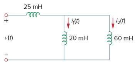
Figure 6.84
For Prob. 6.62.
Expert Solution & Answer
Want to see the full answer?
Check out a sample textbook solution
Students have asked these similar questions
Three capacitors 3 µF, 5µF, and 9µF are connected in parallel with an 9V battery. Determine the: (4) energy supplied by the battery in charging the capacitors.
You have two identical batteries, two identical resistors, and two identical capacitors (you also have infinite ideal wires). Sketch the circuit that includes all of the circuit elements that will cause the capacitors to charge in the least amount of time.
10. Two inductors of 20 mH and 10 mH are connected in series carrying a current of 1 A. Find the total energy stored.
Chapter 6 Solutions
Fundamentals of Electric Circuits
Ch. 6.2 - What is the voltage across a 4.5-F capacitor if...Ch. 6.2 - If a 10-F capacitor is connected to a voltage...Ch. 6.2 - The current through a 100-F capacitor is i(t) = 50...Ch. 6.2 - Figure 6.11 For Practice Prob. 6.4. An initially...Ch. 6.2 - Under dc conditions, find the energy stored in the...Ch. 6.3 - Find the equivalent capacitance seen at the...Ch. 6.3 - Find the voltage across each of the capacitors in...Ch. 6.4 - If the current through a 1-mH inductor is i(t) =...Ch. 6.4 - The terminal voltage of a 2-H inductor is v = 10(1...Ch. 6.4 - Determine vC, iL, and the energy stored in the...
Ch. 6.5 - Calculate the equivalent inductance for the...Ch. 6.5 - In the circuit of Fig. 6.34, i1(t) = 3e2t A. If...Ch. 6.6 - The integrator in Fig. 6.35(b) has R = 100 k, C =...Ch. 6.6 - The differentiator in Fig. 6.37 has R = 100 k and...Ch. 6.6 - Design an analog computer circuit to solve the...Ch. 6 - What charge is on a 5-F capacitor when it is...Ch. 6 - Capacitance is measured in: (a)coulombs (b)joules...Ch. 6 - When the total charge in a capacitor is doubled,...Ch. 6 - Can the voltage waveform in Fig. 6.42 be...Ch. 6 - The total capacitance of two 40-mF...Ch. 6 - In Fig. 6.43, if i = cos 4t and v = sin 4t, the...Ch. 6 - A 5-H inductor changes its current by 3 A in 0.2...Ch. 6 - If the current through a 10-mH inductor increases...Ch. 6 - Inductors in parallel can be combined just like...Ch. 6 - Prob. 10RQCh. 6 - If the voltage across a 7.5-F capacitor is 2te3t...Ch. 6 - A 50-F capacitor has energy w(t) = 10 cos2 377t J....Ch. 6 - Design a problem to help other students better...Ch. 6 - A voltage across a capacitor is equal to [2 2...Ch. 6 - The voltage across a 4-F capacitor is shown in...Ch. 6 - The voltage waveform in Fig. 6.46 is applied...Ch. 6 - At t = 0, the voltage across a 25-mF capacitor is...Ch. 6 - A 4-mF capacitor has the terminal voltage v=...Ch. 6 - The current through a 0.5-F capacitor is 6(1 et)...Ch. 6 - The voltage across a 5-mF capacitor is shown in...Ch. 6 - A 4-mF capacitor has the current waveform shown in...Ch. 6 - A voltage of 45e2000t V appears across a parallel...Ch. 6 - Find the voltage across the capacitors in the...Ch. 6 - Series-connected 20- and 60-pF capacitors are...Ch. 6 - Two capacitors (25 and 75 F) are connected to a...Ch. 6 - The equivalent capacitance at terminals a-b in the...Ch. 6 - Determine the equivalent capacitance for each of...Ch. 6 - Find Ceq in the circuit of Fig. 6.52 if all...Ch. 6 - Find the equivalent capacitance between terminals...Ch. 6 - Find the equivalent capacitance at terminals a-b...Ch. 6 - Determine the equivalent capacitance at terminals...Ch. 6 - Obtain the equivalent capacitance of the circuit...Ch. 6 - Using Fig. 6.57, design a problem that will help...Ch. 6 - In the circuit shown in Fig. 6.58 assume that the...Ch. 6 - (a)Show that the voltage-division rule for two...Ch. 6 - Three capacitors, C1 = 5 F, C2 = 10 F, and C3 = 20...Ch. 6 - Given that four 10-F capacitors can be connected...Ch. 6 - Obtain the equivalent capacitance of the network...Ch. 6 - Determine Ceq for each circuit in Fig. 6.61....Ch. 6 - Assuming that the capacitors are initially...Ch. 6 - If v(0) = 0, find v(t), i1(t), and i2(t) in the...Ch. 6 - In the circuit in Fig. 6.64, let is = 4.5e2t mA...Ch. 6 - Obtain the Thevenin equivalent at the terminals,...Ch. 6 - The current through a 25-mH inductor is 10et/2 A....Ch. 6 - An inductor has a linear change in current from...Ch. 6 - Design a problem to help other students better...Ch. 6 - The current through a 12-mH inductor is 4 sin 100t...Ch. 6 - The current through a 40-mH inductor is i(t)= 0,...Ch. 6 - The voltage across a 50-mH inductor is given by...Ch. 6 - The current through a 5-mH inductor is shown in...Ch. 6 - The voltage across a 2-H inductor is 20(1 e2t) V....Ch. 6 - If the voltage waveform in Fig. 6.67 is applied...Ch. 6 - The current in a 150-mH inductor increases from 0...Ch. 6 - A 100-mH inductor is connected in parallel with a...Ch. 6 - If the voltage waveform in Fig. 6.68 is applied to...Ch. 6 - Find vC, iL, and the energy stored in the...Ch. 6 - For the circuit in Fig. 6.70, calculate the value...Ch. 6 - Under steady-state dc conditions, find i and v in...Ch. 6 - Find the equivalent inductance of the circuit in...Ch. 6 - An energy-storage network consists of...Ch. 6 - Determine Leq at terminals a-b of the circuit in...Ch. 6 - Using Fig. 6.74, design a problem to help other...Ch. 6 - Find Leq at the terminals of the circuit in Fig....Ch. 6 - Find the equivalent inductance looking into the...Ch. 6 - Find Leq in each of the circuits in Fig. 6.77....Ch. 6 - Find Leq in the circuit of Fig. 6.78. Figure 6.78...Ch. 6 - Determine Leq that may be used to represent the...Ch. 6 - The current waveform in Fig. 6.80 flows through a...Ch. 6 - (a) For two inductors in series as in Fig....Ch. 6 - In the circuit of Fig. 6.82, io(0) = 2 A....Ch. 6 - Consider the circuit in Fig. 6.83. Find: (a) Leq,...Ch. 6 - Consider the circuit in Fig. 6.84. Given that v(t)...Ch. 6 - In the circuit of Fig. 6.85, sketch vo. Figure...Ch. 6 - The switch in Fig. 6.86 has been in position A for...Ch. 6 - The inductors in Fig. 6.87 are initially charged...Ch. 6 - The current i(t) through a 20-mH inductor is...Ch. 6 - An op amp integrator has R = 50 k and C = 0.04 F....Ch. 6 - A 6-V dc voltage is applied to an integrator with...Ch. 6 - An op amp integrator with R = 4 M and C = 1 F has...Ch. 6 - Using a single op amp, a capacitor, and resistors...Ch. 6 - Show how you would use a single op amp to generate...Ch. 6 - At t = 1.5 ms, calculate vo due to the cascaded...Ch. 6 - Show that the circuit in Fig. 6.90 is a...Ch. 6 - The triangular waveform in Fig. 6.91(a) is applied...Ch. 6 - An op amp differentiator has R = 250 k and C = 10...Ch. 6 - A voltage waveform has the following...Ch. 6 - The output vo of the op amp circuit in Fig....Ch. 6 - Prob. 78PCh. 6 - Figure 6.93 presents an analog computer designed...Ch. 6 - Design an analog computer to simulate the...Ch. 6 - Design an op amp circuit such that vo=10vs+2vsdt...Ch. 6 - Your laboratory has available a large number of...Ch. 6 - An 8-mH inductor is used in a fusion power...Ch. 6 - A square-wave generator produces the voltage...Ch. 6 - An electric motor can be modeled as a series...
Knowledge Booster


Learn more about
Need a deep-dive on the concept behind this application? Look no further. Learn more about this topic, electrical-engineering and related others by exploring similar questions and additional content below.Similar questions
- Three capacitors 3 µF, 5µF, and 9µF are connected in parallel with an 9V battery. Determine the: (2) charge drawn from the battery.arrow_forwardThe voltage source is at a constant level for a long time, which we approximate as infinite. This is the circuit: The voltage drop across the capacitor rises from 0 to ℰ. Note that ℰ is never actually known in the measurement. In fact, the oscilloscope voltage is decalibrated, so that, whatever ℰ is, ℰ is at the top line while zero is at the bottom line. We don't measure voltage levels, but rather 1/2, 1/4, and 1/8 the maximum. Kirchhoff's voltage law give: ℰ = IR + Q/C or the following: dQdt=−1RC(Q−EC)dQdt=−1RC(Q−ℰC) The solution for the capacitor voltage is VC(t)=E(1−e−t/RC)VC(t)=ℰ(1−e−t/RC) The voltage is zero at t = 0, t is the rising time, and you have to know when the rising begins.arrow_forwardunder steady-state dc conditions find i and v in the circuit in Fig. 6.71arrow_forward
- Three capacitors 8µF, 6µF, and 4µF are connected in series with an 9V battery. Determine the: (4) energy supplied by the battery in charging the capacitors.arrow_forwardGive reason : a) The total resistance in a circuit with parallel resistors increases , if one of the parallel resistors opens . b) If the inductor is charged it acts as an open circuit. c) If the capacitor is fully discharged it acts as a short circuit .arrow_forwardThe current in a 0.6 microfarad capacitor is 0 [A] for time less than zero and 3cos50000t [A] for time greater than or equal to zero. Find v(t) and the maximum power delivered to the capacitor.arrow_forward
- Three capacitors 3 µF, 5µF, and 9µF are connected in parallel with an 9V battery. Determine the: (5) energy stored in each capacitor.arrow_forwardA 100-uF capacitor is charged by a constant current of 1mA. Find the voltage across the capacitor at t = 4s. Assume V(0) = 0 V.arrow_forward6.35 An inductor has a linear change in current from50 mA to 100 mA in 2 ms and induces a voltage of160 mV. Calculate the value of the inductorarrow_forward
- A 5000 uF capacitor is charged by a steady current of 0.5 mA for 30 s. Calculate (a) the charge supplied, and (b) the capacitor p.d. at 30 sarrow_forwardThe current I(t) through a 5.0-mH inductor varies with time, as shown below. The resistance of the inductor is 5.0 Ω. Calculate the voltage across the inductor at t = 2.0 ms, t = 4.0 ms, and t = 8.0 ms .arrow_forwardA circuit comprises the following components: a 270 µF capacitor connected inseries with a 42 kΩ resistor. The circuit is connected to an 24 V dc supply. find The initial value of the current flowing.arrow_forward
arrow_back_ios
SEE MORE QUESTIONS
arrow_forward_ios
Recommended textbooks for you
 Introductory Circuit Analysis (13th Edition)Electrical EngineeringISBN:9780133923605Author:Robert L. BoylestadPublisher:PEARSON
 Delmar's Standard Textbook Of ElectricityElectrical EngineeringISBN:9781337900348Author:Stephen L. HermanPublisher:Cengage Learning
 Programmable Logic ControllersElectrical EngineeringISBN:9780073373843Author:Frank D. PetruzellaPublisher:McGraw-Hill Education
 Fundamentals of Electric CircuitsElectrical EngineeringISBN:9780078028229Author:Charles K Alexander, Matthew SadikuPublisher:McGraw-Hill Education
 Electric Circuits. (11th Edition)Electrical EngineeringISBN:9780134746968Author:James W. Nilsson, Susan RiedelPublisher:PEARSON
 Engineering ElectromagneticsElectrical EngineeringISBN:9780078028151Author:Hayt, William H. (william Hart), Jr, BUCK, John A.Publisher:Mcgraw-hill Education,
Introductory Circuit Analysis (13th Edition)
Electrical Engineering
ISBN:9780133923605
Author:Robert L. Boylestad
Publisher:PEARSON
Delmar's Standard Textbook Of Electricity
Electrical Engineering
ISBN:9781337900348
Author:Stephen L. Herman
Publisher:Cengage Learning
Programmable Logic Controllers
Electrical Engineering
ISBN:9780073373843
Author:Frank D. Petruzella
Publisher:McGraw-Hill Education
Fundamentals of Electric Circuits
Electrical Engineering
ISBN:9780078028229
Author:Charles K Alexander, Matthew Sadiku
Publisher:McGraw-Hill Education
Electric Circuits. (11th Edition)
Electrical Engineering
ISBN:9780134746968
Author:James W. Nilsson, Susan Riedel
Publisher:PEARSON
Engineering Electromagnetics
Electrical Engineering
ISBN:9780078028151
Author:Hayt, William H. (william Hart), Jr, BUCK, John A.
Publisher:Mcgraw-hill Education,
Capacitors Explained - The basics how capacitors work working principle; Author: The Engineering Mindset;https://www.youtube.com/watch?v=X4EUwTwZ110;License: Standard YouTube License, CC-BY