
Concept explainers
Videos
The inductors in Fig. 6.87 are initially charged and are connected to the black box at t = 0. If i1(0) = 4 A, i2(0) = −2 A, and v(t) = 50e−200t mV, t ≥ 0, find:
- (a) the energy initially stored in each inductor,
- (b) the total energy delivered to the black box from t = 0 to t = ∞,
- (c) i1(t) and i2(t), t ≥ 0,
- (d) i(t), t ≥ 0.
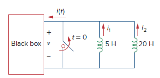
Figure 6.87
For Prob. 6.65.
(a)
Calculate the initial energy stored in each inductor for the given initial conditions.
Answer to Problem 65P
The energy stored initially in each inductor
Explanation of Solution
Given data:
The Black box connects across the initially charged inductors at
The initial current of inductor
The initial current of inductor
The voltage across the inductors and black box is same. That is,
Formula used:
Write the formula to find the energy stored in an inductor.
Calculation:
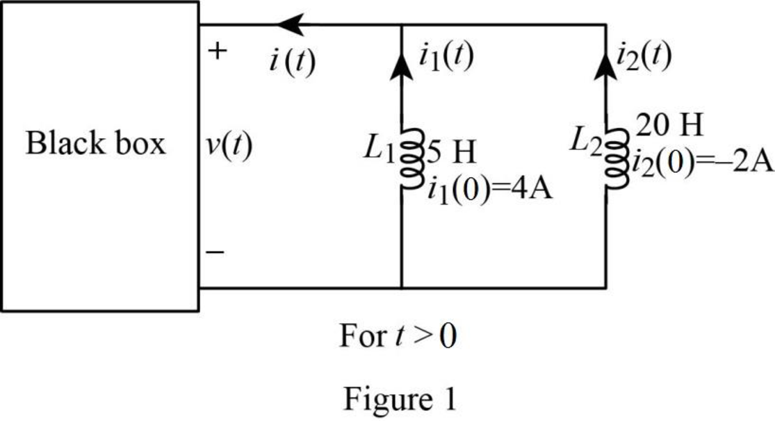
Re-draw the given figure as shown in Figure 1.
Using the formula in equation (1), the energy stored initially in inductor
Substitute
Using the formula in equation (1), the energy stored initially in inductor
Substitute
Conclusion:
Thus, the energy stored initially in each inductor
(b)
Calculate the total energy delivered to the black box by the inductors for
Answer to Problem 65P
The total energy delivered to the black box by the inductors is
Explanation of Solution
Given data:
Refer to Part (a).
Formula used:
Write the formula to find the total energy delivered to the black box by the inductors from
Here,
Calculation:
The total energy delivered to the black box in period of
Substitute
Conclusion:
Thus, the total energy delivered to the black box by the inductors is
(c)
Calculate the currents in each inductor for the period of
Answer to Problem 65P
The currents
Explanation of Solution
Given data:
Refer to Part (a).
Formula used:
Write the formula to find the current through an inductor.
Here,
Calculation:
Using the formula in equation (3), the current through an inductor
Since the black box and both inductors are in parallel,
Substitute
In the Figure 1, currents
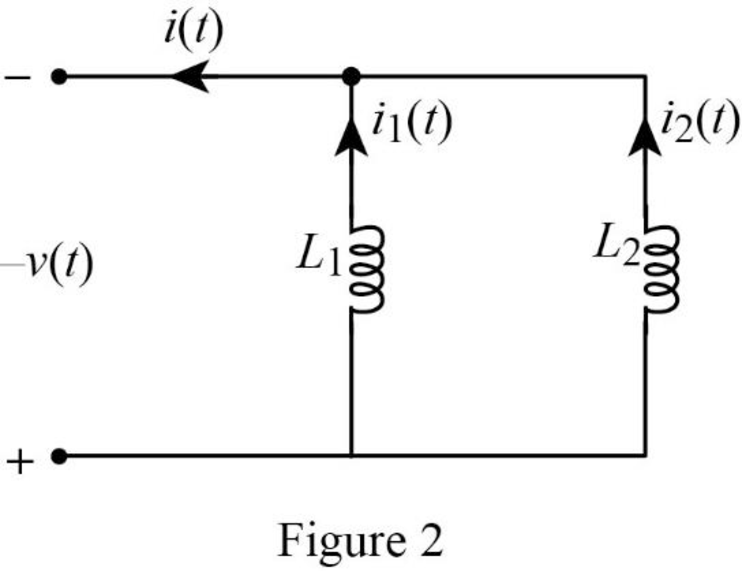
From Figure 2, the current
Substitute
Reduce the equation as follows.
Using the formula in equation (3), the current
Substitute
Consider reversing polarities for voltage
Substitute
Reduce the equation as follows.
Conclusion:
Thus, the currents
(d)
Find the current
Answer to Problem 65P
The current
Explanation of Solution
Given data:
Refer to part (a).
Formula used:
Write the formula for the current
Here,
Calculation:
Refer to part (c), the currents
Substitute
Conclusion:
Thus, the current
Want to see more full solutions like this?
Chapter 6 Solutions
FUNDAMENTALS OF ELEC.CIRC.(LL) >CUSTOM<


- The voltage across a 5 μF capacitor is known to be vc=500te−2500t V for t≥0. Find the maximum energy stored in the capacitors and the time when the maximum occurs.arrow_forwardA 5000 uF capacitor is charged by a steady current of 0.5 mA for 30 s. Calculate (a) the charge supplied, and (b) the capacitor p.d. at 30 sarrow_forwardA 20-uF capacitor has a voltage of 5V across it at t=0. If a constant current of 30mA flows through the capacitor, how long will it take for the capacitor to charge up to 180 uC?arrow_forward
- A capacitor is constructed with parallel metal plates, If the plate separation is 2 mm and the capacitance is given to 1 nano Farads, determine the area of the parallel plates of the device.arrow_forwardA 125 F capacitor that has an initial voltage of 25 V is charged with a current that varies with time according to the equation I = t(t^2 + 6.83)^0.5 A . Find the voltage across the capacitor after 1 s.arrow_forwardShown below are four RC circuits labelled A, B, C, and D. Each has some combination of batteries with emf E = 4.5 V, resistors with resistance R = 15 kΩ, and a capacitor with capacitance C = 2.5 µF. For each circuit, find the amount of time (in seconds, to two significant digits) it takes for the current to decay by a factor of 1/e.arrow_forward
- 2. Suppose you want a capacitor bank with a total capacitance of 0.750 F and you possess numerous 1.50 mF capacitors. What is the smallest number you could hook together to achieve your goal, and how would you connect them?arrow_forwardA capacitor is charged with 50 mC in a time of 20 µS. If the energy stored in the capacitor is 5 J, find (i) voltage across the capacitor, (ii) current through the capacitor and (iii) value of capacitance.arrow_forwardA capacitor with a capacitance of 32 microfarads is discharged through a resistance of 53 kilo-ohms. How many milliseconds does it take for the voltage to drop to 1/e of its initial value. Here "e" is the base of natural logarithms, about 2.718 .arrow_forward
- Two capacitors, of capacitance 3µF and 5µF, are connected as shown to batteries A and B which have EMF 4 V and 12 V respectively. What is the energy stored in each of the capacitors? Calculate also the stored energy in each capacitor when the terminals of battery A are reversed, and when the battery B is disconnected, and the points X and Y are connected together.arrow_forwardThe switch has been in position 1 for a long time. At t = 0, the switch moves instantaneously to position 2. Find the value of R so that 10% of the initial energy stored in the 10mH inductor is dissipated in R in micro-second. Use KCL/KVL and refrain from using formulas.arrow_forwardCan somebody explain why the inductors are open circuit and the capacitor is short circuited. Given that: The presence of a voltage source indicates an infinite size, which may be stated in the circuit as Vs(t)= δ(t).arrow_forward
 Introductory Circuit Analysis (13th Edition)Electrical EngineeringISBN:9780133923605Author:Robert L. BoylestadPublisher:PEARSON
 Delmar's Standard Textbook Of ElectricityElectrical EngineeringISBN:9781337900348Author:Stephen L. HermanPublisher:Cengage Learning
 Programmable Logic ControllersElectrical EngineeringISBN:9780073373843Author:Frank D. PetruzellaPublisher:McGraw-Hill Education
 Fundamentals of Electric CircuitsElectrical EngineeringISBN:9780078028229Author:Charles K Alexander, Matthew SadikuPublisher:McGraw-Hill Education
 Electric Circuits. (11th Edition)Electrical EngineeringISBN:9780134746968Author:James W. Nilsson, Susan RiedelPublisher:PEARSON
 Engineering ElectromagneticsElectrical EngineeringISBN:9780078028151Author:Hayt, William H. (william Hart), Jr, BUCK, John A.Publisher:Mcgraw-hill Education,