
FUND.OF ELECTRIC CIRCUIT(LL)-PACKAGE
6th Edition
ISBN: 9781260263794
Author: Alexander
Publisher: MCG
expand_more
expand_more
format_list_bulleted
Videos
Textbook Question
Chapter 6, Problem 73P
Show that the circuit in Fig. 6.90 is a noninverting integrator.
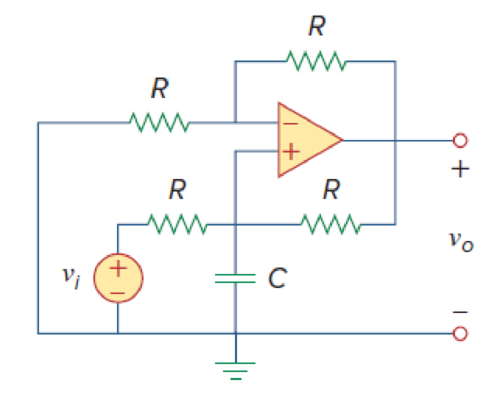
Figure 6.90
For Prob. 6.73.
Expert Solution & Answer
Want to see the full answer?
Check out a sample textbook solution
Students have asked these similar questions
4- Find the number of times the following loop is performed in 8051 microcontroller
ORG 0H
MOV R6, #200
BACK: MOV R5, #100
HERE: DJNZ R5, HERE
DJNZ R6, BACK
END
Please explain this circuit because I still don't understand, this circuit is used for an experiment to calculate SR (Slew Rate) on the op amp
under steady-state dc conditions find i and v in the circuit in Fig. 6.71
Chapter 6 Solutions
FUND.OF ELECTRIC CIRCUIT(LL)-PACKAGE
Ch. 6.2 - What is the voltage across a 4.5-F capacitor if...Ch. 6.2 - If a 10-F capacitor is connected to a voltage...Ch. 6.2 - The current through a 100-F capacitor is i(t) = 50...Ch. 6.2 - Figure 6.11 For Practice Prob. 6.4. An initially...Ch. 6.2 - Under dc conditions, find the energy stored in the...Ch. 6.3 - Find the equivalent capacitance seen at the...Ch. 6.3 - Find the voltage across each of the capacitors in...Ch. 6.4 - If the current through a 1-mH inductor is i(t) =...Ch. 6.4 - The terminal voltage of a 2-H inductor is v = 10(1...Ch. 6.4 - Determine vC, iL, and the energy stored in the...
Ch. 6.5 - Calculate the equivalent inductance for the...Ch. 6.5 - In the circuit of Fig. 6.34, i1(t) = 3e2t A. If...Ch. 6.6 - The integrator in Fig. 6.35(b) has R = 100 k, C =...Ch. 6.6 - The differentiator in Fig. 6.37 has R = 100 k and...Ch. 6.6 - Design an analog computer circuit to solve the...Ch. 6 - What charge is on a 5-F capacitor when it is...Ch. 6 - Capacitance is measured in: (a)coulombs (b)joules...Ch. 6 - When the total charge in a capacitor is doubled,...Ch. 6 - Can the voltage waveform in Fig. 6.42 be...Ch. 6 - The total capacitance of two 40-mF...Ch. 6 - In Fig. 6.43, if i = cos 4t and v = sin 4t, the...Ch. 6 - A 5-H inductor changes its current by 3 A in 0.2...Ch. 6 - If the current through a 10-mH inductor increases...Ch. 6 - Inductors in parallel can be combined just like...Ch. 6 - Prob. 10RQCh. 6 - If the voltage across a 7.5-F capacitor is 2te3t...Ch. 6 - A 50-F capacitor has energy w(t) = 10 cos2 377t J....Ch. 6 - Design a problem to help other students better...Ch. 6 - A voltage across a capacitor is equal to [2 2...Ch. 6 - The voltage across a 4-F capacitor is shown in...Ch. 6 - The voltage waveform in Fig. 6.46 is applied...Ch. 6 - At t = 0, the voltage across a 25-mF capacitor is...Ch. 6 - A 4-mF capacitor has the terminal voltage v=...Ch. 6 - The current through a 0.5-F capacitor is 6(1 et)...Ch. 6 - The voltage across a 5-mF capacitor is shown in...Ch. 6 - A 4-mF capacitor has the current waveform shown in...Ch. 6 - A voltage of 45e2000t V appears across a parallel...Ch. 6 - Find the voltage across the capacitors in the...Ch. 6 - Series-connected 20- and 60-pF capacitors are...Ch. 6 - Two capacitors (25 and 75 F) are connected to a...Ch. 6 - The equivalent capacitance at terminals a-b in the...Ch. 6 - Determine the equivalent capacitance for each of...Ch. 6 - Find Ceq in the circuit of Fig. 6.52 if all...Ch. 6 - Find the equivalent capacitance between terminals...Ch. 6 - Find the equivalent capacitance at terminals a-b...Ch. 6 - Determine the equivalent capacitance at terminals...Ch. 6 - Obtain the equivalent capacitance of the circuit...Ch. 6 - Using Fig. 6.57, design a problem that will help...Ch. 6 - In the circuit shown in Fig. 6.58 assume that the...Ch. 6 - (a)Show that the voltage-division rule for two...Ch. 6 - Three capacitors, C1 = 5 F, C2 = 10 F, and C3 = 20...Ch. 6 - Given that four 10-F capacitors can be connected...Ch. 6 - Obtain the equivalent capacitance of the network...Ch. 6 - Determine Ceq for each circuit in Fig. 6.61....Ch. 6 - Assuming that the capacitors are initially...Ch. 6 - If v(0) = 0, find v(t), i1(t), and i2(t) in the...Ch. 6 - In the circuit in Fig. 6.64, let is = 4.5e2t mA...Ch. 6 - Obtain the Thevenin equivalent at the terminals,...Ch. 6 - The current through a 25-mH inductor is 10et/2 A....Ch. 6 - An inductor has a linear change in current from...Ch. 6 - Design a problem to help other students better...Ch. 6 - The current through a 12-mH inductor is 4 sin 100t...Ch. 6 - The current through a 40-mH inductor is i(t)= 0,...Ch. 6 - The voltage across a 50-mH inductor is given by...Ch. 6 - The current through a 5-mH inductor is shown in...Ch. 6 - The voltage across a 2-H inductor is 20(1 e2t) V....Ch. 6 - If the voltage waveform in Fig. 6.67 is applied...Ch. 6 - The current in a 150-mH inductor increases from 0...Ch. 6 - A 100-mH inductor is connected in parallel with a...Ch. 6 - If the voltage waveform in Fig. 6.68 is applied to...Ch. 6 - Find vC, iL, and the energy stored in the...Ch. 6 - For the circuit in Fig. 6.70, calculate the value...Ch. 6 - Under steady-state dc conditions, find i and v in...Ch. 6 - Find the equivalent inductance of the circuit in...Ch. 6 - An energy-storage network consists of...Ch. 6 - Determine Leq at terminals a-b of the circuit in...Ch. 6 - Using Fig. 6.74, design a problem to help other...Ch. 6 - Find Leq at the terminals of the circuit in Fig....Ch. 6 - Find the equivalent inductance looking into the...Ch. 6 - Find Leq in each of the circuits in Fig. 6.77....Ch. 6 - Find Leq in the circuit of Fig. 6.78. Figure 6.78...Ch. 6 - Determine Leq that may be used to represent the...Ch. 6 - The current waveform in Fig. 6.80 flows through a...Ch. 6 - (a) For two inductors in series as in Fig....Ch. 6 - In the circuit of Fig. 6.82, io(0) = 2 A....Ch. 6 - Consider the circuit in Fig. 6.83. Find: (a) Leq,...Ch. 6 - Consider the circuit in Fig. 6.84. Given that v(t)...Ch. 6 - In the circuit of Fig. 6.85, sketch vo. Figure...Ch. 6 - The switch in Fig. 6.86 has been in position A for...Ch. 6 - The inductors in Fig. 6.87 are initially charged...Ch. 6 - The current i(t) through a 20-mH inductor is...Ch. 6 - An op amp integrator has R = 50 k and C = 0.04 F....Ch. 6 - A 6-V dc voltage is applied to an integrator with...Ch. 6 - An op amp integrator with R = 4 M and C = 1 F has...Ch. 6 - Using a single op amp, a capacitor, and resistors...Ch. 6 - Show how you would use a single op amp to generate...Ch. 6 - At t = 1.5 ms, calculate vo due to the cascaded...Ch. 6 - Show that the circuit in Fig. 6.90 is a...Ch. 6 - The triangular waveform in Fig. 6.91(a) is applied...Ch. 6 - An op amp differentiator has R = 250 k and C = 10...Ch. 6 - A voltage waveform has the following...Ch. 6 - The output vo of the op amp circuit in Fig....Ch. 6 - Prob. 78PCh. 6 - Figure 6.93 presents an analog computer designed...Ch. 6 - Design an analog computer to simulate the...Ch. 6 - Design an op amp circuit such that vo=10vs+2vsdt...Ch. 6 - Your laboratory has available a large number of...Ch. 6 - An 8-mH inductor is used in a fusion power...Ch. 6 - A square-wave generator produces the voltage...Ch. 6 - An electric motor can be modeled as a series...
Additional Engineering Textbook Solutions
Find more solutions based on key concepts
What is the color code for a 365- five-band precision resistor with a tolerance of 5 percent?
ELECTRICITY FOR TRADES (LOOSELEAF)
Find I0 and I1 in the circuit in Fig.P2.12.
Basic Engineering Circuit Analysis
Analog Voltmeter Design Figure P2-98(a) shows a voltmeter circuit consisting of a D'Arsonval meter, two series ...
ANALYSIS+DESIGN OF LINEAR CIRCUITS(LL)
How many coulombs do 93.8 1016 electrons represent?
Principles Of Electric Circuits
Identify the type of input and output configuration for each diff-amp in Figure 18-35.
Electronics Fundamentals: Circuits, Devices & Applications
Electric power systems provide energy in a variety of commercial and industrial settings. Make a list of system...
Principles and Applications of Electrical Engineering
Knowledge Booster


Learn more about
Need a deep-dive on the concept behind this application? Look no further. Learn more about this topic, electrical-engineering and related others by exploring similar questions and additional content below.Similar questions
- Design an op amp circuit that can perform the following operations Vout = 16*(dVin/dt) For 3 different inputs, Vout = 4*(V1+ V2+ V3)arrow_forwardA 50 Hz, 200 Vpeak voltage source supplies power to a load consisting of a resistor in parallel with a capacitor.The active power delivered by the source is 500 W and the apparent power is 800 VA. Calculate the value of the capacitor in micro-Farad.arrow_forwardThe current I(t) through a 5.0-mH inductor varies with time, as shown below. The resistance of the inductor is 5.0 Ω. Calculate the voltage across the inductor at t = 2.0 ms, t = 4.0 ms, and t = 8.0 ms .arrow_forward
- An energy-storage network consists of series- connected 16- and 14-mH inductors in parallel with series-connected 24- and 36-mH inductors. Calculate the equivalent inductance of this circuit. Enter your answer in units of mH.arrow_forwardSOLVE STEP BY STEP IN DIGITAL FORMAT A 12 volt battery is connected to a series circuit in which the inductor is 1/4 Henry and the resistance is 25 Ohm. Determine the current i, if the initial current is zero.arrow_forwardThe voltage source is at a constant level for a long time, which we approximate as infinite. This is the circuit: The voltage drop across the capacitor rises from 0 to ℰ. Note that ℰ is never actually known in the measurement. In fact, the oscilloscope voltage is decalibrated, so that, whatever ℰ is, ℰ is at the top line while zero is at the bottom line. We don't measure voltage levels, but rather 1/2, 1/4, and 1/8 the maximum. Kirchhoff's voltage law give: ℰ = IR + Q/C or the following: dQdt=−1RC(Q−EC)dQdt=−1RC(Q−ℰC) The solution for the capacitor voltage is VC(t)=E(1−e−t/RC)VC(t)=ℰ(1−e−t/RC) The voltage is zero at t = 0, t is the rising time, and you have to know when the rising begins.arrow_forward
- An op amp has a GBP of 106 . A 0.3 μV sinusoidal signal at 5 KHz is required to beamplified to 5 V. Calculate the gains and draw the schematic circuit to achieve this.arrow_forwardDesign a monostable multivibrator to have a pulsewidth of 20 s and a recovery time of 5 s. Usethe circuit with ±5 V supplies.arrow_forwardThe voltage across a 5 μF capacitor is known to be vc=500te−2500t V for t≥0. Find the power at the terminals of the capacitor when t=100 μs.arrow_forward
- An inductor of 2 henrys is connected in series with a resistor of 12 ohms, a capacitor of 1 / 16 farad, and a 300-volt battery. Initially, the charge on the capacitor is zero and the current is zero. Formulate an initial value problem modeling this electric circuit.arrow_forwardA 500 Ω resistor, a 16 mH inductor, and a 25 nF capacitor are connected inparallel. Compute the numerical values of the zeros and poles.arrow_forwardDetemine vc, iL, as well energy stored in the capacitor and inductor in the circuit under DC conditionsarrow_forward
arrow_back_ios
SEE MORE QUESTIONS
arrow_forward_ios
Recommended textbooks for you
 Introductory Circuit Analysis (13th Edition)Electrical EngineeringISBN:9780133923605Author:Robert L. BoylestadPublisher:PEARSON
 Delmar's Standard Textbook Of ElectricityElectrical EngineeringISBN:9781337900348Author:Stephen L. HermanPublisher:Cengage Learning
 Programmable Logic ControllersElectrical EngineeringISBN:9780073373843Author:Frank D. PetruzellaPublisher:McGraw-Hill Education
 Fundamentals of Electric CircuitsElectrical EngineeringISBN:9780078028229Author:Charles K Alexander, Matthew SadikuPublisher:McGraw-Hill Education
 Electric Circuits. (11th Edition)Electrical EngineeringISBN:9780134746968Author:James W. Nilsson, Susan RiedelPublisher:PEARSON
 Engineering ElectromagneticsElectrical EngineeringISBN:9780078028151Author:Hayt, William H. (william Hart), Jr, BUCK, John A.Publisher:Mcgraw-hill Education,
Introductory Circuit Analysis (13th Edition)
Electrical Engineering
ISBN:9780133923605
Author:Robert L. Boylestad
Publisher:PEARSON
Delmar's Standard Textbook Of Electricity
Electrical Engineering
ISBN:9781337900348
Author:Stephen L. Herman
Publisher:Cengage Learning
Programmable Logic Controllers
Electrical Engineering
ISBN:9780073373843
Author:Frank D. Petruzella
Publisher:McGraw-Hill Education
Fundamentals of Electric Circuits
Electrical Engineering
ISBN:9780078028229
Author:Charles K Alexander, Matthew Sadiku
Publisher:McGraw-Hill Education
Electric Circuits. (11th Edition)
Electrical Engineering
ISBN:9780134746968
Author:James W. Nilsson, Susan Riedel
Publisher:PEARSON
Engineering Electromagnetics
Electrical Engineering
ISBN:9780078028151
Author:Hayt, William H. (william Hart), Jr, BUCK, John A.
Publisher:Mcgraw-hill Education,
02 - Sinusoidal AC Voltage Sources in Circuits, Part 1; Author: Math and Science;https://www.youtube.com/watch?v=8zMiIHVMfaw;License: Standard Youtube License