Videos
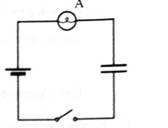
Suppose an uncharged capacitor is connected in series with a battery and bulb as shown.
-
1. Predict the behavior of the bulb when the switch is closed. Explain.
Set up the circuit and check your prediction. If your prediction is in conflict with your observation, how can you account for your observation?
-
2. Without using a voltmeter, determine the potential difference across the capacitor at the following times:
• just after the switch is closed. Explain how you can tell. (Hint: Compare the brightness of the bulb to the brightness of a bulb connected to a battery in a single-bulb circuit without a capacitor.)
• a long time after the switch is closed. Explain how you can tell.
Use a voltmeter to check your predictions. (Hint: Be sure to discharge the capacitor completely after each observation.)
Want to see the full answer?
Check out a sample textbook solution
Chapter 6 Solutions
Tutorials In Introductory Physics: Homework
Additional Science Textbook Solutions
College Physics: A Strategic Approach (4th Edition)
Conceptual Integrated Science
Conceptual Physics (12th Edition)
The Cosmic Perspective (8th Edition)
College Physics (10th Edition)
Sears And Zemansky's University Physics With Modern Physics


- Question 1 For the circuit in the Figure EL2-1 below, RT= > R1 >1.0k Ω R9 510 3 R10 1300 1. Determine if the following statements are TRUE or FALSE. Write in the blank space T if the statement is TRUE or F if the statement is FALSE. • Resistors R1 and R2 are in parallel. Answer: • The current that flows through resistor R4 equals the sum of the currents through resistor R6 and resistor R7. Answer: • The equivalent resistance of R3 and R8 is 168.2 Q. Answer: • The voltage drop accross R6 and R7 is the same. Q. Answer: • The equivalent resistance of R9 and R10 is 181 Q. Answer: 2. Determine the total equivalent resistor RT (shown in Figure EL2-2 below) of the circuit shown in Figure 1. Give your answer to 1 decimal place (1 d.p.) R2 3.0k 3 R3 >8.20 7 R8 1600 2 R4 160 Figure EL2-1 - Resisitve DC circuit Downloadable image RT R5 750 R6 820 >R7 >1500 Figure EL2-2 - Equivalent circuit to Figure EL1V2-1 Downloadable imagearrow_forwardUse your electric symbol guide. . Draw a circuit for each of the following scenarios. • Label the circuit with all information given in the prompt ○ Volts V unit of electric potential о Watts W unit of power (use) о Ohms = Qunit of resistance о Series: Items are all on one loop connected to the sides of the power source (battery) ○ Parallel: items are on separate loops connected to the sides of the power source (battery) Prompts 1. Draw a circuit with a 9 volt battery, a switch, and a 9 watt light bulb 2. Draw a circuit with a 120 volt ac power source and two 70 watt light bulbs in parallel. 3. Draw a circuit with a 120 volt ac power source, a 110 watt resistor, and a 70 watt bulb in parallel and 2 switches (one on each branch).arrow_forwardConsider the circuit shown in the figure (Figure 1). The values of the different components are as follows: • • Ebattery = emf = 9.0 Volts r (internal resistance of the battery) = 1.52 Figure R₁ = 5S R₂ = 152 R3 = 40 S2 I₁ switch R₁ + R₂ battery Q R₂ 13 Part A Use Kirchoff's rules to calculate 1₁, 12, and 13. Enter your answer as 3 values, separated by a comma (11, 12, 13) 11, 12, 13 = Submit 197| ΑΣΦ VO Provide Feedback Previous Answers Request Answer X Incorrect; Try Again; 4 attempts remaining ? Aarrow_forward
- • Part A In the circuit shown in the figure (Figure 1), S1 has been closed for a long enough time so that the current reads a steady 3.50 A. Suddenly, S2 is closed and Si is opened at the same instant. What is the maximum charge that the capacitor will receive? ΑΣΦ ? Qmaz mC Submit Previous Answers Request Answer A 2.0 mH 5.00 μF Rarrow_forwardDC Voltmeters and Ammeters• Explain why a voltmeter must be connected in parallel with the circuit.• Draw a diagram showing an ammeter correctly connected in a circuit.• Describe how a galvanometer can be used as either a voltmeter or an ammeter.• Find the resistance that must be placed in series with a galvanometer to allow it to be used as a voltmeter with agiven reading.• Explain why measuring the voltage or current in a circuit can never be exact.arrow_forwardA portion of a larger circuit is shown in the diagram below. The potential drop between points b and a is Vba = 4.0 V. Similarly, Vcb =3.5 V, Vcd = 2.0 V, Vdf = -0.5 V. Here, if Vba is greater than zero, then a is at a higher potential than b. Answer the following questions in SI units. 1. What is the potential difference Vgf? 2. What is the potential difference Vca? 3. What is the potential difference Vag?arrow_forward
- Two long, straight conducting wires with linear mass density A are suspended from cords so that they are each horizontal, parallel to each other, and a distance d apart. The back ends of the wires are connected to one another by a slack, low-resistance connecting wire. A charged capacitor (capacitance C) is now added to the system; the positive plate of the capacitor (initial charge +Qo) is connected to the front end of one of the wires, and the negative plate of the capacitor (initial charge-Qo) is connected to the front end of the other wire (see the figure (Figure 1)). Both of these connections are also made by slack, low-resistance wires. When the connection is made, the wires are pushed aside by the repulsive force between the wires, and each wire has an initial horizontal velocity of magnitude vo. Assume that the time for the capacitor to discharge is negligible compared to the time it takes for any appreciable displacement in the position of the wires to occur. Part A Determine…arrow_forwardPhysics Questionarrow_forwardPart A The voltage across the terminals of a 9.0 V battery is 8.3 V when the battery is connected to a 45 Q load. What is the battery's internal resistance? Express your answer with the appropriate units. • View Available Hint(s) Value Unitsarrow_forward
- Instructions Use your electric symbol guide. • Draw a circuit for each of the following scenarios. • Label the circuit with all information given in the prompt 0 Volts = V unit of electric potential Prompts о Watts W unit of power (use) 0 ° Ohms=unit of resistance Series: Items are all on one loop connected to the sides of the power source (battery) ° Parallel: items are on separate loops connected to the sides of the power source (battery) 8. Draw a circuit with a 3.7 volt battery, a 10 ohm buzzer, a 12 ohm resistor, and a 15 ohm bulb all in parallel. 9. Draw a circuit with two (2) 9 volt batteries with one 10 watt bulb on 2 parallel branches 10. Draw a circuit with a 120 volts ac power source, six (6) 10 watt light bulbs and a switch on one circuit, and a 10 ohm resistor and 45 watt lightbulb and a switch on a parallel circuit.arrow_forwardQ3: Simplify the following circuit, and draw the simplified circuit? B C•arrow_forwardCan you help the question and its attachments?arrow_forward
 Physics for Scientists and Engineers, Technology ...PhysicsISBN:9781305116399Author:Raymond A. Serway, John W. JewettPublisher:Cengage Learning