Videos
6.119 through 6.121 Each of the frames shown consists of two L-shaped members connected by two rigid links. For each frame, determine the reactions at the supports and indicate whether the frame is rigid.
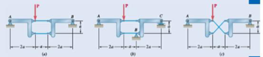
Fig. P6.121
The reactions at the frame and the rigidness of the frame.
Answer to Problem 6.121P
The reactions at the frame for figure (a) is
Explanation of Solution
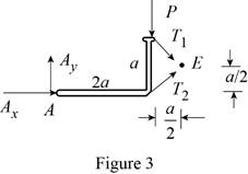
The following figure gives the free body diagram of the first part of the member in figure P6.121(a).
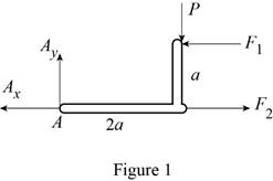
Write the equation to find the moment of force.
Here,
Write the equation to find the total moment about the point
Write the equations for equilibrium for the free body diagram in figure 1.
Here,
The following figure gives the free body diagram of the second part of the member in figure P6.121(a).
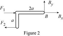
Write the equations for equilibrium for the free body diagram in figure 2.
Here,
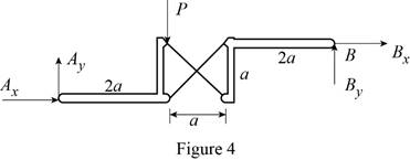
The following figure gives the free body diagram of the first part of the member in figure P6.119(b).
Write the equations for equilibrium for the free body diagram in figure 3.
Here,
The following figure gives the free body diagram of the second part of the member in figure P6.119(b).
Write the equations for equilibrium for the free body diagram in figure 4.
Here,
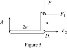
The following figure gives the free body diagram of the member in figure P6.119(c).
Write the equations for equilibrium for the free body diagram in figure 5.
Here,
The following figure gives the free body diagram of right part of the member in figure P6.119(c).
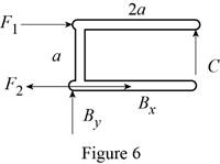
Write the equations for equilibrium for the free body diagram in figure 6.
Here,
Write the expression to find the magnitude of the vector from its components.
Here,
Write the equation to find the angle of orientation of the vector
Conclusion:
Solve equation (I) using figure 1.
Rewrite the above equation.
Solve equation (III) using figure 1.
Rewrite the above equation.
Solve equation (IV) using figure 2.
Rewrite the above equation.
Solve equation (V) using figure 2.
Substitute
Solve equation (VI) using figure 2.
Substitute
Rewrite equation (XIV) in terms of the vector
Substitute
Rewrite equation (XV) in terms of the vector
Substitute
Rewrite equation (XIV) in terms of the vector
Substitute
Solve equation (VII) using figure 3.
Rewrite the above equation.
Solve equation (VIII) using figure 4.
Rewrite the above equation.
Solve the conditions obtained from figure 3 and 4.
Solve equation (IX) using figure 5.
Rewrite the above equation to find
Solve equation (X) using figure 5.
Substitute
Solve equation (XI) using figure 5.
Substitute
Solve equation (XII) using figure 6.
Substitute
Solve equation (XII) to the right using figure 6.
Substitute
Solve equation (XII) upwards using figure 6.
Substitute
Therefore, the reactions at the frame for figure (a) is
Want to see more full solutions like this?
Chapter 6 Solutions
EBK VECTOR MECHANICS FOR ENGINEERS: STA


- A foldable tray for the paper supply of a photocopy machine is shown. The tray is supported by a single hinge at A and two slotted links (one on each side of the tray). If the stack of paper weighs 14 N and other weights may be neglected, determine the reactions at point B for one of the links when D = 190 mm.arrow_forwardA 14 ft long beam ABC supports a frictionless pulley with 12 in radius at point B, located 10 ft from the left end. The cable DC supports 150 lb weight W as shown. Determine and direction of the reaction at the roller at C. Determine the magnitude and direction of the reaction at pin A.arrow_forwardA 5 x 8-ft sign of uniform density weighs 270 lb and is supported by a ball-and-socket joint at A and by two cables. Determine the tension in each cable and the reaction at A.arrow_forward
- 4.108 - A 2250 N marquee, 2,4 x 3 m, is held in a horizontal position bytwo horizontal hinges at A and B and by a cable CD attached to a point D located 1,5m directly above B. Determine the tension in the cable and the components of the reactions at the hinges.arrow_forwardThe cab and motor units of the front-end loader shown are connected by a vertical pin located 2 m behind the cab wheels. The distance from C to D is 1 m. The center of gravity of the 300-kN motor unit is located at Gm, while the centers of gravity of the 100-kN cab and 75-kN load are located, respectively, at Gc and Gl. Knowing that the front-end loader is at rest with its brakes released, determine(a) the reactions at each of the four wheels, (b) the forces exertedon the motor unit at C and D.arrow_forwardTwo 9-in.-diameter pipes (pipe 1 and pipe 2) are supported every 7.5 ft by a small frame like that shown. Knowing that the combined weight of each pipe and its contents is 30 lb/ft and assuming frictionless surfaces, determine the components of the reactions at A and G.arrow_forward
- A uniform circular rod with a weight of 8 lb and radius of 10 in. is attached to a pin at C and to the cable AB . Determine (a) the tension in the cable, (b) the reaction at C.arrow_forwardA freight car is stopped on a track at an angle of 25o to the vertical. The gross weight of the wagon and its load is 36kN and acts at a point 750 mm from the track, in the middle between the two axles. The wagon is supported by a cable 600 mm from the track. Determine the traction on the cable and the reaction on each pair of wheels.arrow_forwardA uniform rod AB with a length of l and weight of W is suspended from two cords AC and BC of equal length. Determine the angle 0 corresponding to the equilibrium position when a couple M is applied to the rod.arrow_forward
- A 48-in. boom is held by a ball-and-socket joint at C and by two cables BF and DAE; cable DAE passes around a frictionless pulley at A. For the loading shown, determine the tension in each cable and the reaction at C.arrow_forwardA 48-in. boom is held by a ball-and-socket joint at C and by two cables BF and DAF passes around a frictionless pulley at A . For the loading shown, determine the tension in each cable and the reaction at C.arrow_forwardThe solid bar shown is supported by simple bushings that exert reaction forces on the bar. Determine the reactions at supports A, B, and C.arrow_forward
 International Edition---engineering Mechanics: St...Mechanical EngineeringISBN:9781305501607Author:Andrew Pytel And Jaan KiusalaasPublisher:CENGAGE L