
a.
Find the current values
a.
Answer to Problem 1P
The current values
Explanation of Solution
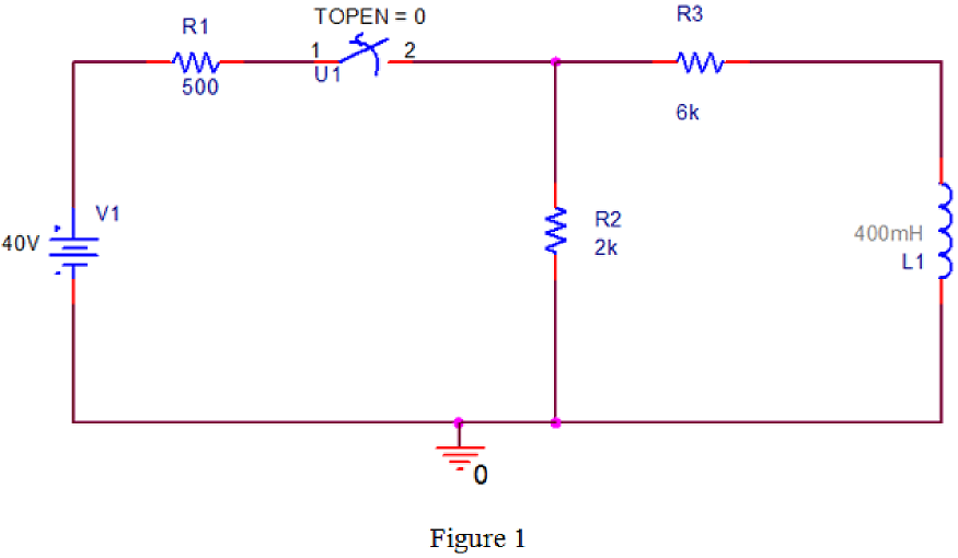
PSPICE Circuit:
Refer to the Figure P7.1 in the textbook.
Draw the given circuit diagram in PSPICE as shown in Figure 1.
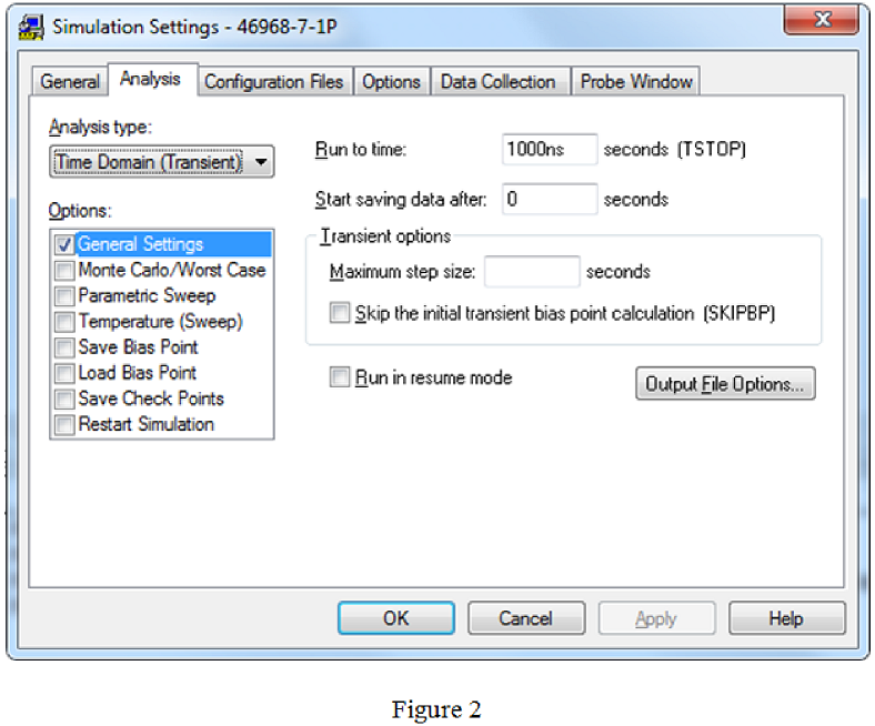
Simulation settings:
Provide the simulation settings as shown in Figure 2.
PSPICE output:
After run the PSPICE circuit a black output screen will be displayed. Right click on the mouse by keeping cursor on the output screen, click the option “Add Trace” and type the expression “-I(R3)” in trace expression box.
The current plot
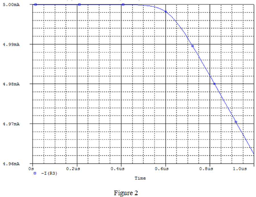
From PSPICE output, the initial values of current are,
Similarly, type the expression “-I(R2)” in trace expression box to obtain the current
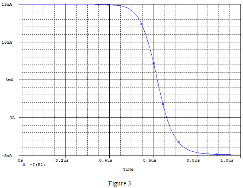
From PSPICE output, the initial values of current are,
Conclusion:
Therefore, the values of
b.
Find the current values
b.
Answer to Problem 1P
The current values
Explanation of Solution
Calculation:
From Figure 2 and Figure 3, the current values are,
Conclusion:
Therefore, the current values
c.
Find the expression
c.
Answer to Problem 1P
The expression
Explanation of Solution
Calculation:
Find the equivalent resistance after the switch is opened at
Find time constant from the circuit diagram.
Here,
L is the inductance.
Substitute
The expression
Substitute 5 mA for
Conclusion:
Therefore, the expression
d.
Find the expression
d.
Answer to Problem 1P
The expression
Explanation of Solution
Calculation:
Find the equivalent resistance after the switch is opened at
Find time constant from the circuit diagram.
Here,
L is the inductance.
Substitute
The expression
Substitute –5 mA for
Conclusion:
Therefore, the expression
e.
Explain the reason for why
e.
Explanation of Solution
Calculation:
The current in the resistor changes instantaneously. The switching operation makes the current
Conclusion:
Therefore, the reason for why
Want to see more full solutions like this?
Chapter 7 Solutions
ELECTRIC CIRCUITS& INTR. TO PSPIC W/MAS

 Introductory Circuit Analysis (13th Edition)Electrical EngineeringISBN:9780133923605Author:Robert L. BoylestadPublisher:PEARSON
 Delmar's Standard Textbook Of ElectricityElectrical EngineeringISBN:9781337900348Author:Stephen L. HermanPublisher:Cengage Learning
 Programmable Logic ControllersElectrical EngineeringISBN:9780073373843Author:Frank D. PetruzellaPublisher:McGraw-Hill Education
 Fundamentals of Electric CircuitsElectrical EngineeringISBN:9780078028229Author:Charles K Alexander, Matthew SadikuPublisher:McGraw-Hill Education
 Electric Circuits. (11th Edition)Electrical EngineeringISBN:9780134746968Author:James W. Nilsson, Susan RiedelPublisher:PEARSON
 Engineering ElectromagneticsElectrical EngineeringISBN:9780078028151Author:Hayt, William H. (william Hart), Jr, BUCK, John A.Publisher:Mcgraw-hill Education,