
Concept explainers
Find the vertical deflection at joint E of the frame using virtual work method.
Answer to Problem 50P
The vertical deflection at joint E of the frame is
Explanation of Solution
Given information:
The frame is given in the Figure.
The value of E is 200 GPa and I is
Apply the sign conventions for calculating reactions, forces and moments using the three equations of equilibrium as shown below.
- For summation of forces along x-direction is equal to zero
- For summation of forces along y-direction is equal to zero
- For summation of moment about a point is equal to zero
Calculation:
Consider the real system.
Draw a diagram showing all the given real loads acting on it.
Let the bending moment due to real load be
Sketch the real system of the frame as shown in Figure 1.
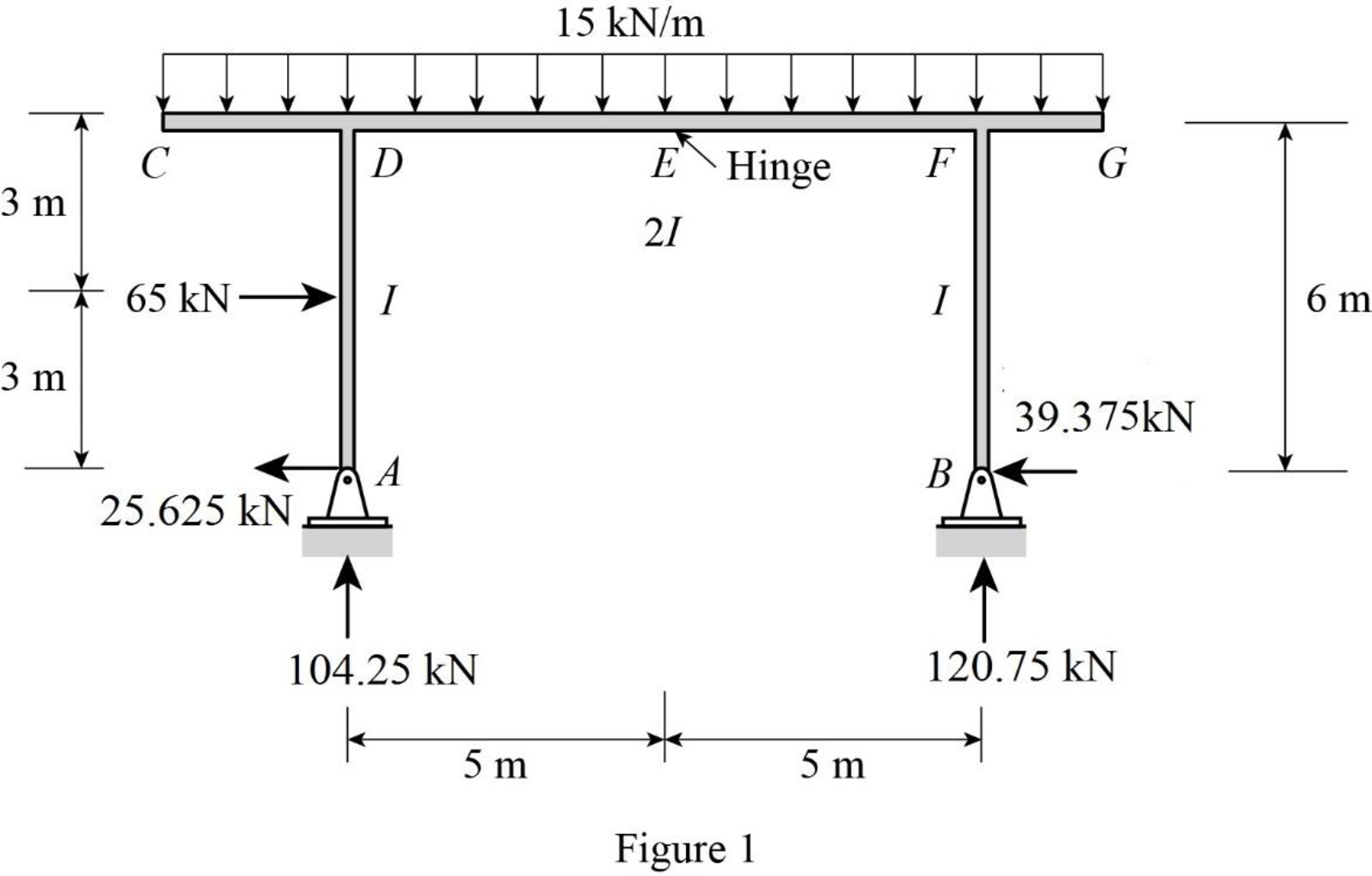
Find the reactions at the supports A and B:
Summation of moments about A is equal to 0.
Summation of forces along y-direction is equal to 0.
Consider ACDE, summation of moments about E is equal to 0.
Summation of forces along x-direction is equal to 0.
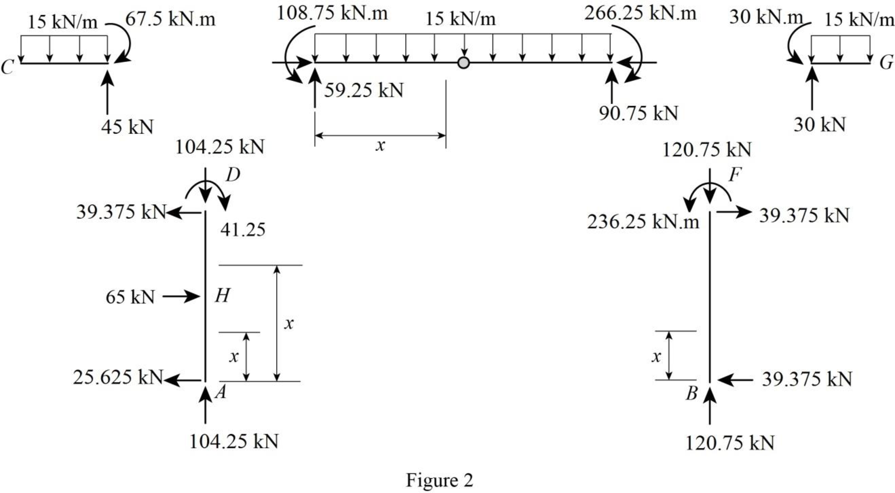
Sketch the member end forces of the real system as shown in Figure 2.
Consider the virtual system.
Draw a diagram of frame without the given real loads. For vertical deflection apply unit load at the joint in the vertical direction.
Let the bending moment due to virtual load be
Sketch the virtual system of the frame with unit load at joint E as shown in Figure 3.
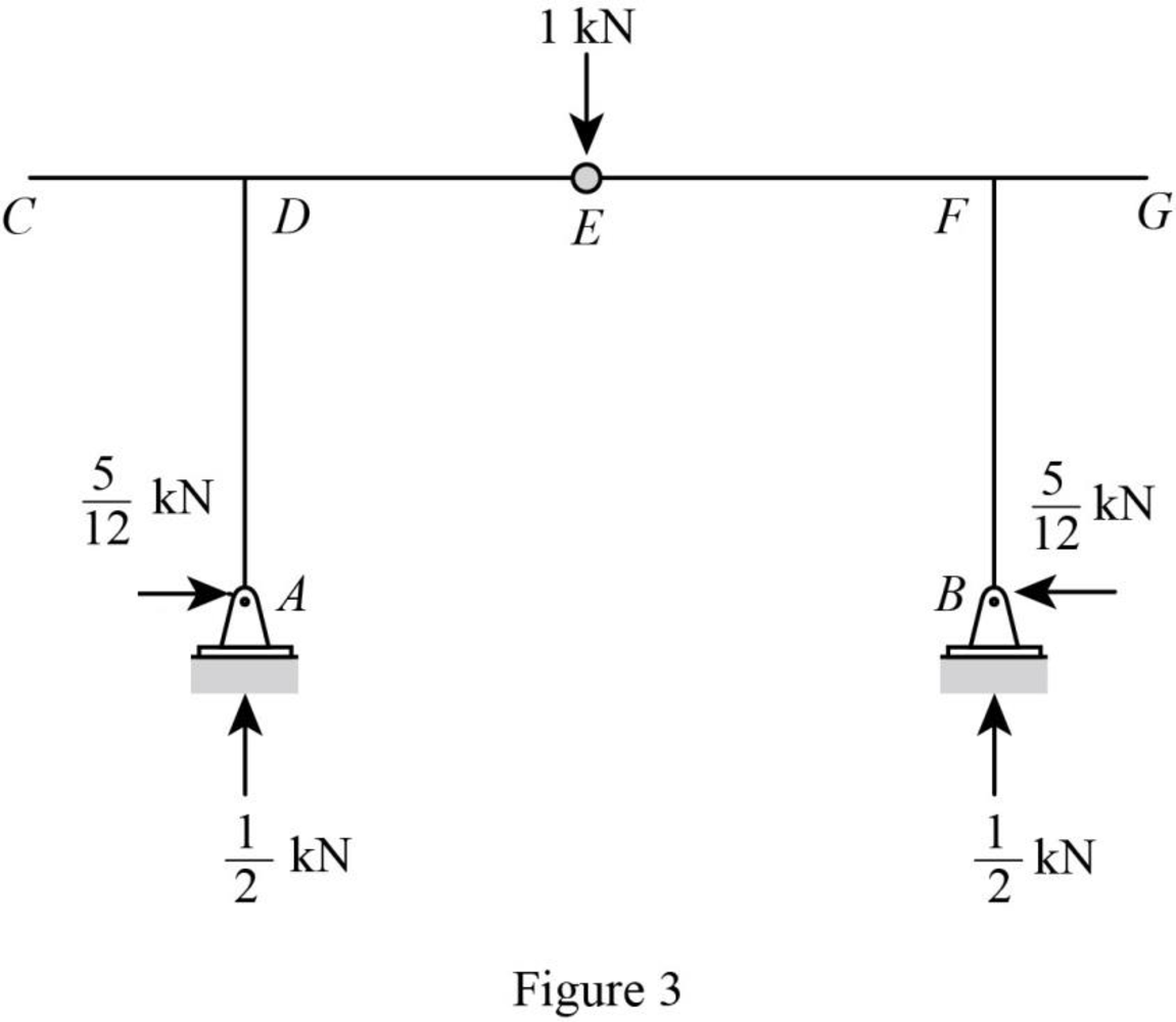
Find the reactions at the supports A and B:
Summation of moments about A is equal to 0.
Summation of forces along y-direction is equal to 0.
Consider ACDE, summation of moments about E is equal to 0.
Summation of forces along x-direction is equal to 0.
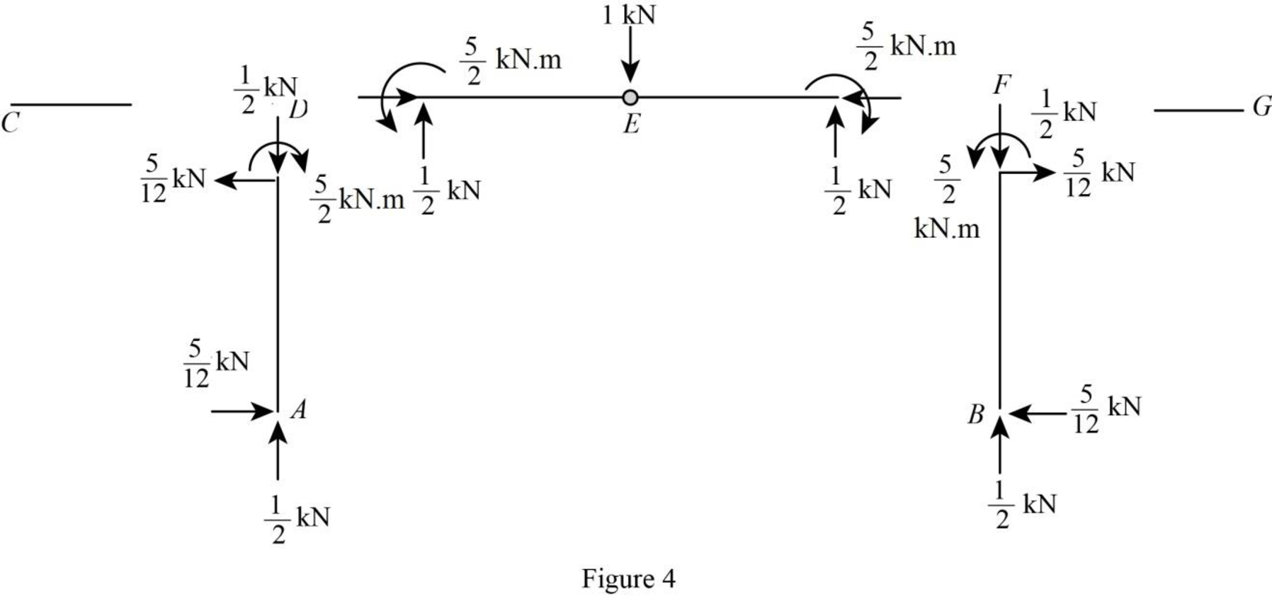
Sketch the member end forces of the virtual system as shown in Figure 4.
Find the equations for M and
| Segment | x-coordinate |
M |
| |
| Origin | Limits (m) | |||
| AH | A | |||
| HD | A | |||
| BF | B | |||
| DE | D | |||
| FE | F | |||
Find the vertical deflection at E using the virtual work expression:
Moment of inertia of span AH is I, moment of inertia of span HD is I, moment of inertia of span BF is I, moment of inertia of span DE is 2I, and moment of inertia of span FE is 2I.
Rearrange Equation (1) for the limits
Substitute
Substitute 200 GPa for E and
Therefore, the vertical deflection at E is
Want to see more full solutions like this?
Chapter 7 Solutions
EBK STRUCTURAL ANALYSIS


