Programmable Logic Controllers - With Access
5th Edition
ISBN: 9781259933523
Author: Petruzella
Publisher: MCG
expand_more
expand_more
format_list_bulleted
Textbook Question
Chapter 7, Problem 5P
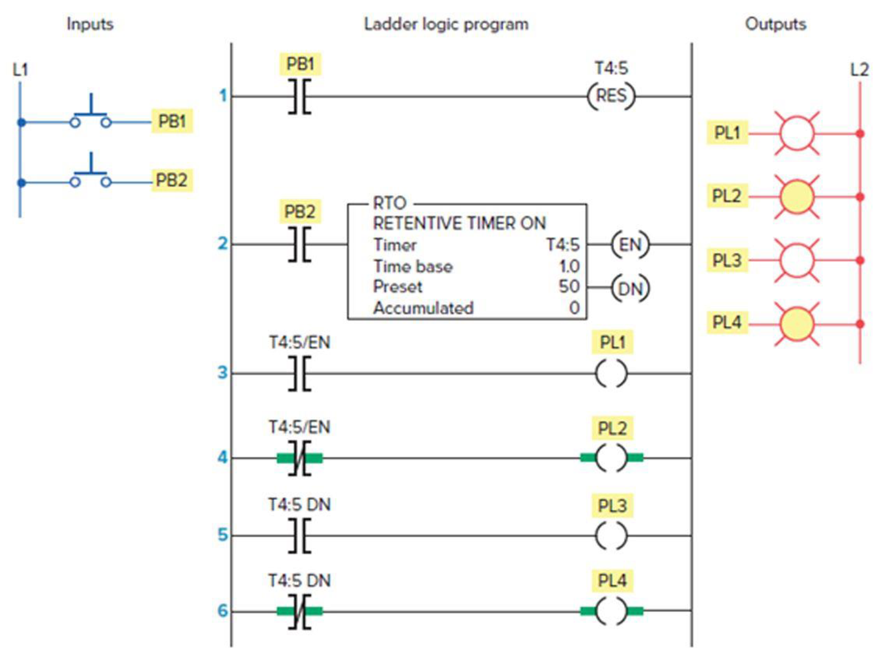
Study the ladder logic
- a. What type of timer has been programmed?
- b. What is the length of the time-delay period?
- c. When does the timer start timing?
- d. When is the timer reset?
- e. When will rung 3 be true?
- f. When will rung 5 be true?
- g. When will output PL4 be energized?
- h. Assume that your accumulated time value is up to 020 and power to your system is lost. What will your accumulated time value be when power is restored?
- i. What happens if inputs PB1 and PB2 are both true at the same time?
Expert Solution & Answer
Want to see the full answer?
Check out a sample textbook solution
Students have asked these similar questions
Describe how the clocking procedure works.
Why did the program fail to capture the output of the circuit? Think about the timing and make the necessary correction. Compile, and re-run. The correct output should be0because: 1 and (not 1) = 1 and 0 = 0.
using the verilog
Given the input timing diagram of the inputs R and S, determine the output Q for an active-low input SR latch and answer the questions below. Write the letter that best represent your answer. Assume Q is zero before time A.
1. What is the status of the flip-flop at A?
a. no change b. set c. reset d. undefined
2. What is the value of Q at A?
a. zero b. one
3. What is the status of the flip-flop at B?
a. no change b. set c. reset d. undefined
4. What is the value of Q at B?
a. zero b. one
5. What is the status of the flip-flop at C?
a. no change b. set c. reset d. undefined
6. What is the value of Q at C?
a. zero b. one
7. What is the status of the flip-flop at D?
a. no change b. set c. reset d. undefined
8. What is the value of Q at D?
a. zero b. one
9. What is the status of the…
Chapter 7 Solutions
Programmable Logic Controllers - With Access
Ch. 7 - Prob. 1RQCh. 7 - Prob. 2RQCh. 7 - Prob. 3RQCh. 7 - Prob. 4RQCh. 7 - a. What are the two methods commonly used to...Ch. 7 - Prob. 6RQCh. 7 - Prob. 7RQCh. 7 - Prob. 8RQCh. 7 - For a TOF timer: a. When is the enable bit of a...Ch. 7 - Explain what each of the following quantities...
Ch. 7 - State the method used to reset the accumulated...Ch. 7 - Study the ladder logic program in Figure 7-40 and...Ch. 7 - Study the ladder logic program in Figure 7-42, and...Ch. 7 - Prob. 6PCh. 7 - Prob. 7PCh. 7 - Prob. 8PCh. 7 - Prob. 9PCh. 7 - Prob. 10PCh. 7 - Prob. 11PCh. 7 - Prob. 13PCh. 7 - When the lights are turned off in a building, an...
Additional Engineering Textbook Solutions
Find more solutions based on key concepts
The job of the _____ is to fetch instructions, carry out the operations commanded by the instructions, and prod...
Starting Out With Visual Basic (7th Edition)
The ____________ is always transparent.
Web Development and Design Foundations with HTML5 (8th Edition)
Porter’s competitive forces model: The model is used to provide a general view about the firms, the competitors...
Management Information Systems: Managing The Digital Firm (16th Edition)
What output will the following lines of code display on the screen? cout "The works of Wolfgang\ninclude the f...
Starting Out with C++: Early Objects
How does a computers main memory differ from its auxiliary memory?
Java: An Introduction to Problem Solving and Programming (7th Edition)
A byte is made up of eight a. CPUs b. addresses c. variables d. bits
Starting Out with Java: From Control Structures through Objects (7th Edition) (What's New in Computer Science)
Knowledge Booster

Similar questions
- Draw a ladder logic diagram for the timer scenario shown.arrow_forwardDraw a ladder logic diagram for the timer scenario shown (draw out the timer delays too)arrow_forwardDraw a ladder logic diagram for the timer scenarios given below. (I've asked you guys PLC questions multiple times please just answer them). IT'S A SOFTWARE QUESTION STOP REJECTING IT.arrow_forward
- Python Question Which of the following is true of short-circuiting? a) It can be used for 'or', but not 'and'.b) It can be used for both 'and' and 'or'; its use depends on particular values.c) It is used on any Boolean expression; it doesn't matter what the values are.d) 'x or y' is always the same as 'y or x' because of short-circuiting.arrow_forward1. write a truth table using this symbol: --> 2. write the inputs for the truth table to the left of the --> and write the outputs for the truth table to the right of the --> 3. write the compliment, or NOT using ' Given the following Boolean equation: F = A XOR B XOR C XOR D that represents a digital logic circuit where the output is F and the inputs A, B, C, and D, write the truth table for the Boolean equation.arrow_forwardCounter implementation using timer 1 module in timer mode.Each incremental value will have delay of last 5 seconds, code should be in Mikro C for PIC16F877A.arrow_forward
- Q1: What inputs and output does the system detect and where are these locations? Q2: What logic gates are used for the landing gear warning logic module?arrow_forwardUsing the ASM chart in the figure, design a control logic using One Flip-flop per State. Answer the following: Note: Type N/A if not applicable Use upper case letters, it is case sensitive Use apostrophe to indicate complemented variable For every term in the expression, follow the sequence of the alphabet. The input equation to D Flip-flop T0, DT0 = The input equation to D Flip-flop T1, DT1 = The input equation to D Flip-flop T2, DT2 = The input equation to D Flip-flop T3, DT3 = The input equation to D Flip-flop T4, DT4 =arrow_forwardDevelop the ladder logic diagram to fill the tank. 1. Filling the water tank up to 80%. When the tank is filled, turn ON the heater to raise the temperature up to 70-degree C.2. when this temperature is reached, turn OFF the heater & open the outlet valve.3. When the level in the tank falls below 10%, closes the output valve and start filling the tank again.4. A digital counter is used to monitor the number of times the tank is emptied (reaches 10%). Once the counter reaches to 8 times, the system is stopped.arrow_forward
- 2. Draw the timing diagram for the Clocked SR flip-flop at each of the instants t0 to t6 as described in the class meeting. a. at t0, Q is low, S is low, R is low b. at t0, Q is high, S is low, R is low Be sure to include the clock signal in the timing diagram.arrow_forwardWrite the word TRUE if the statement is correct If the statement is false, replace the word's that, if substituted for the underlined word/s, would make the statement correct. Flip-flops are asynchronous bi-stable devices because there can only be two states. Negative edged triggered flip-flop has a bubble on the clock input signal which means that the circuit will only respond to negative The S-R flip-flop is a single-input version of the J-K flip-flop formed by tying both inputs togetherarrow_forward(d) Now disconnect the switches and probe, and in their place connect Multisim’s LogicConverter. Use the Logic Converter to generate the circuit’s truth table, and make sure that itmatches the one you just wrote down. Also use the Logic Converter to generate thesimplified expression for the circuit, and record this expression below:X = _______________________________________________________ This is part d other parts are in picarrow_forward
arrow_back_ios
SEE MORE QUESTIONS
arrow_forward_ios
Recommended textbooks for you
 Database System ConceptsComputer ScienceISBN:9780078022159Author:Abraham Silberschatz Professor, Henry F. Korth, S. SudarshanPublisher:McGraw-Hill Education
 Starting Out with Python (4th Edition)Computer ScienceISBN:9780134444321Author:Tony GaddisPublisher:PEARSON
 Digital Fundamentals (11th Edition)Computer ScienceISBN:9780132737968Author:Thomas L. FloydPublisher:PEARSON
 C How to Program (8th Edition)Computer ScienceISBN:9780133976892Author:Paul J. Deitel, Harvey DeitelPublisher:PEARSON
 Database Systems: Design, Implementation, & Manag...Computer ScienceISBN:9781337627900Author:Carlos Coronel, Steven MorrisPublisher:Cengage Learning
 Programmable Logic ControllersComputer ScienceISBN:9780073373843Author:Frank D. PetruzellaPublisher:McGraw-Hill Education
Database System Concepts
Computer Science
ISBN:9780078022159
Author:Abraham Silberschatz Professor, Henry F. Korth, S. Sudarshan
Publisher:McGraw-Hill Education
Starting Out with Python (4th Edition)
Computer Science
ISBN:9780134444321
Author:Tony Gaddis
Publisher:PEARSON
Digital Fundamentals (11th Edition)
Computer Science
ISBN:9780132737968
Author:Thomas L. Floyd
Publisher:PEARSON
C How to Program (8th Edition)
Computer Science
ISBN:9780133976892
Author:Paul J. Deitel, Harvey Deitel
Publisher:PEARSON
Database Systems: Design, Implementation, & Manag...
Computer Science
ISBN:9781337627900
Author:Carlos Coronel, Steven Morris
Publisher:Cengage Learning
Programmable Logic Controllers
Computer Science
ISBN:9780073373843
Author:Frank D. Petruzella
Publisher:McGraw-Hill Education