Engineering Mechanics: Statics, Student Value Edition (14th Edition)
14th Edition
ISBN: 9780134056388
Author: Russell C. Hibbeler
Publisher: PEARSON
expand_more
expand_more
format_list_bulleted
Videos
Textbook Question
Chapter 7.1, Problem 21P
Point E is located just to the left of 800 N force.
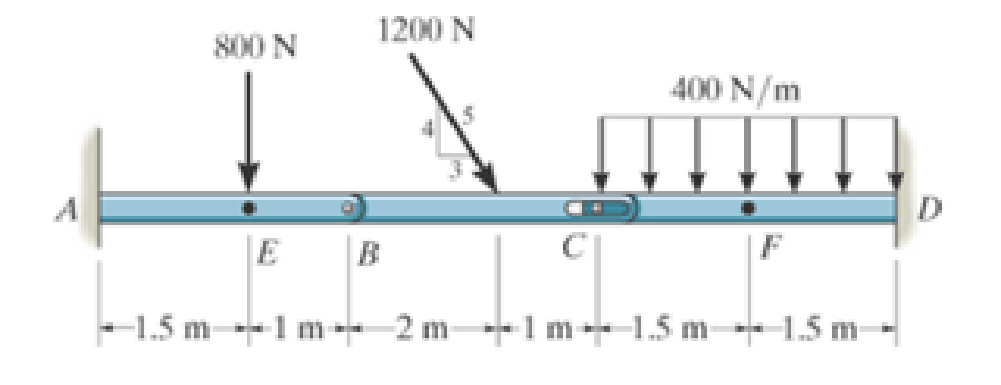
Prob. 7-21
Expert Solution & Answer
Want to see the full answer?
Check out a sample textbook solution
Students have asked these similar questions
prob 4
ᴀɴ ᴀɪʀ-ꜱᴛᴀɴᴅᴀʀᴅ ʙʀᴀʏᴛᴏɴ ᴄʏᴄʟᴇ ʜᴀꜱ ᴀɪʀ ᴇɴᴛᴇʀ ᴛʜᴇ ᴄᴏᴍᴘʀᴇꜱꜱᴏʀ ᴀᴛ 25°ᴄ ᴀɴᴅ 101 ᴋᴘᴀ. ᴛʜᴇ ᴘʀᴇꜱꜱᴜʀᴇ ʀᴀᴛɪᴏ ɪꜱ 8, ᴀɴᴅ ᴛʜᴇ ᴍᴀxɪᴍᴜᴍ ᴀʟʟᴏᴡᴀʙʟᴇ ᴛᴇᴍᴘᴇʀᴀᴛᴜʀᴇ ɪɴ ᴛʜᴇ ᴄʏᴄʟᴇ ɪꜱ 1077°ᴄ. ɪꜰ ᴛʜᴇ ᴄʏᴄʟᴇ ɪꜱ ɪɴᴛᴇɴᴅᴇᴅ ᴛᴏ ᴘʀᴏᴅᴜᴄᴇ ᴛʜᴇ ᴛʜᴇᴏʀᴇᴛɪᴄᴀʟ ᴍᴀxɪᴍᴜᴍ ɴᴇᴛ ᴡᴏʀᴋ ɢɪᴠᴇɴ ᴛʜᴇ ᴛᴇᴍᴘᴇʀᴀᴛᴜʀᴇ ʟɪᴍɪᴛꜱ:
ᴀ. ᴅᴇᴛᴇʀᴍɪɴᴇ ᴛʜᴇ ᴛᴇᴍᴘᴇʀᴀᴛᴜʀᴇꜱ ᴀᴛ ᴇᴀᴄʜ ᴘᴏɪɴᴛꜱ ᴀʀᴏᴜɴᴅ ᴛʜᴇ ᴄʏᴄʟᴇ ɪɴ °ᴄ.
ʙ. ᴅᴇᴛᴇʀᴍɪɴᴇ ᴛʜᴇ ᴄᴏᴍᴘʀᴇꜱꜱᴏʀ ᴡᴏʀᴋ ᴘᴇʀ ᴋɪʟᴏɢʀᴀᴍ ᴏꜰ ᴀɪʀ.
ᴄ. ᴅᴇᴛᴇʀᴍɪɴᴇ ᴛʜᴇ ᴛᴜʀʙɪɴᴇ ᴡᴏʀᴋ ᴘᴇʀ ᴋɪʟᴏɢʀᴀᴍ ᴏꜰ ᴀɪʀ.
ᴅ. ᴅᴇᴛᴇʀᴍɪɴᴇ ᴛʜᴇ ᴄʏᴄʟᴇ ᴛʜᴇʀᴍᴀʟ ᴇꜰꜰɪᴄɪᴇɴᴄʏ ɪɴ %.
ᴇ. ᴅʀᴀᴡ ᴛʜᴇ ᴘ-ᴠ ᴀɴᴅ ᴛ-ꜱ ᴅɪᴀɢʀᴀᴍꜱ ᴏꜰ ᴛʜᴇ
The rod has a circular cross section. If it is made of an elastic perfectly plastic material, determine the shape factor for the rod.
Chapter 7 Solutions
Engineering Mechanics: Statics, Student Value Edition (14th Edition)
Ch. 7.1 - In each case, calculate the reaction at A and then...Ch. 7.1 - Determine the normal force, shear force, and...Ch. 7.1 - Determine the normal force, shear force, and...Ch. 7.1 - Determine the normal force, shear force, and...Ch. 7.1 - Determine the normal force, shear force, and...Ch. 7.1 - Determine the normal force, shear force, and...Ch. 7.1 - Assume A is pinned and B is a roller. Prob. F7-6Ch. 7.1 - Determine the shear force and moment at points C...Ch. 7.1 - Assume the support at B is a roller. Point C is...Ch. 7.1 - Determine the internal normal force, shear force,...
Ch. 7.1 - Determine the internal normal force, shear force,...Ch. 7.1 - If a force of 20 lb is applied to the handles,...Ch. 7.1 - Determine the distance a as a fraction of the...Ch. 7.1 - Determine the internal shear force and moment...Ch. 7.1 - Determine the internal shear force and moment...Ch. 7.1 - Take P = 8 kN. Prob. 7-9Ch. 7.1 - Determine the largest vertical load P the frame...Ch. 7.1 - Determine the internal normal force, shear force,...Ch. 7.1 - Determine the distance a between the bearings in...Ch. 7.1 - Point D is located just to the left of the 5-kip...Ch. 7.1 - The shaft is supported by a journal bearing at A...Ch. 7.1 - Determine the internal normal force, shear force,...Ch. 7.1 - Determine the internal normal force, shear force,...Ch. 7.1 - Determine the normal force, shear force, and...Ch. 7.1 - Determine the internal normal force, shear force,...Ch. 7.1 - Prob. 19PCh. 7.1 - Determine the internal normal force, shear force,...Ch. 7.1 - Point E is located just to the left of 800 N...Ch. 7.1 - Point D is located just to the left of the roller...Ch. 7.1 - Determine the internal normal force, shear force,...Ch. 7.1 - Determine the ratio of a/b for which the shear...Ch. 7.1 - Point E is just to the right of the 3-kip load....Ch. 7.1 - Determine the internal normal force, shear force,...Ch. 7.1 - Determine the internal normal force, shear force,...Ch. 7.1 - Point D is located just to the left of the 10-kN...Ch. 7.1 - Determine the normal force, shear force, and...Ch. 7.1 - Determine the normal force, shear force, and...Ch. 7.1 - Determine the internal normal force, shear force,...Ch. 7.1 - Determine the internal normal force, shear force,...Ch. 7.1 - Determine the internal normal force, shear force,...Ch. 7.1 - Determine the internal normal force, shear force,...Ch. 7.1 - If the suspended load has a weight of 2 kN and a...Ch. 7.1 - Determine the internal normal force, shear force,...Ch. 7.1 - Determine the internal normal force, shear force,...Ch. 7.1 - Determine the internal normal force, shear force,...Ch. 7.1 - The distributed loading W = W0 sin , measured per...Ch. 7.1 - Solve Prob. 7-39 for = 120. Probs. 739/40Ch. 7.1 - z components of force and moment at point C in the...Ch. 7.1 - Determine the x, y, z components of force and...Ch. 7.1 - Determine the x, y, z components of internal...Ch. 7.1 - Determine the x, y. z components of internal...Ch. 7.2 - Determine the shear and moment as a function of x,...Ch. 7.2 - Determine the shear and moment as a function of x,...Ch. 7.2 - Determine the shear and moment as a function of x,...Ch. 7.2 - Determine the shear and moment as a function of x,...Ch. 7.2 - Determine the shear and moment as a function of x,...Ch. 7.2 - Determine the shear and moment as a function of x,...Ch. 7.2 - Draw the shear and moment diagrams for the shaft...Ch. 7.2 - Draw the shear and moment diagrams for the beam...Ch. 7.2 - Draw the shear and moment diagrams for the beam...Ch. 7.2 - Draw the shear and moment diagrams for the...Ch. 7.2 - Draw the shear and moment diagrams of the beam (a)...Ch. 7.2 - If L = 9 m, the beam will fail when the maximum...Ch. 7.2 - Draw the shear and moment diagrams for the beam....Ch. 7.2 - Draw the shear and moment diagrams for the beam....Ch. 7.2 - Draw the shear and bending-moment diagrams for the...Ch. 7.2 - The shaft is supported by a smooth thrust bearing...Ch. 7.2 - Draw the shear and moment diagrams for the beam....Ch. 7.2 - Draw the shear and moment diagrams for the beam....Ch. 7.2 - Draw the shear and moment diagrams for the...Ch. 7.2 - Draw the shear and bending-moment diagrams for...Ch. 7.2 - Draw the shear and moment diagrams for the beam....Ch. 7.2 - The shaft is supported by a smooth thrust bearing...Ch. 7.2 - Draw the shear and moment diagrams for the beam....Ch. 7.2 - The beam will fail when the maximum internal...Ch. 7.2 - Draw the shear and moment diagrams for the beam....Ch. 7.2 - Draw the shear and moment diagrams for the beam....Ch. 7.2 - Draw the shear and moment diagrams for the beam....Ch. 7.2 - Draw the shear and moment diagrams for the beam....Ch. 7.2 - Determine the internal normal force, shear force,...Ch. 7.2 - The quarter circular rod lies in the horizontal...Ch. 7.2 - Express the internal shear and moment components...Ch. 7.3 - Draw the shear and moment diagrams for the beam....Ch. 7.3 - Draw the shear and moment diagrams for the beam....Ch. 7.3 - Draw the shear and moment diagrams for the beam....Ch. 7.3 - Draw the shear and moment diagrams for the beam....Ch. 7.3 - Draw the shear and moment diagrams for the beam....Ch. 7.3 - Draw the shear and moment diagrams for the beam....Ch. 7.3 - Draw the shear and moment diagrams for the beam....Ch. 7.3 - Draw the shear and moment diagrams for the beam....Ch. 7.3 - Draw the shear and moment diagrams for the beam....Ch. 7.3 - Draw the shear and moment diagrams for the...Ch. 7.3 - Draw the shear and moment diagrams for the beam....Ch. 7.3 - Draw the shear and moment diagrams for the beam....Ch. 7.3 - Draw the shear and moment diagrams for the beam....Ch. 7.3 - Draw the shear and moment diagrams for the beam....Ch. 7.3 - Draw the shear and moment diagrams for the beam....Ch. 7.3 - Draw the shear and moment diagrams for the shaft....Ch. 7.3 - Draw the shear and moment diagrams for the beam....Ch. 7.3 - The beam consists of three segments pin connected...Ch. 7.3 - Draw the shear and moment diagrams for the beam....Ch. 7.3 - Draw the shear and moment diagrams for the beam....Ch. 7.3 - Draw the shear and moment diagrams for the beam....Ch. 7.3 - Draw the shear and moment diagrams for the beam....Ch. 7.3 - Draw the shear and moment diagrams for the beam....Ch. 7.3 - Draw the shear and moment diagrams for the beam....Ch. 7.3 - Draw the shear and moment diagrams for the beam....Ch. 7.3 - Draw the shear and moment diagrams for the beam....Ch. 7.3 - Draw the shear and moment diagrams for the beam....Ch. 7.3 - Draw the shear and moment diagrams for the beam....Ch. 7.3 - Draw the shear and moment diagrams for the beam....Ch. 7.3 - Draw the shear and moment diagrams for the beam....Ch. 7.4 - The cable supports the three loads shown....Ch. 7.4 - The cable supports the three loads shown....Ch. 7.4 - Determine the tension in each segment of the cable...Ch. 7.4 - The cable supports the loading shown. Determine...Ch. 7.4 - The cable supports the loading shown. Determine...Ch. 7.4 - The cable supports the three loads shown....Ch. 7.4 - The cable supports the three loads shown....Ch. 7.4 - Determine the force P needed to hold the cable in...Ch. 7.4 - Determine the maximum uniform loading w, measured...Ch. 7.4 - The cable is subjected to a uniform loading of w =...Ch. 7.4 - The cable AB is subjected to a uniform loading of...Ch. 7.4 - Prob. 105PCh. 7.4 - If yB = 1.5 ft. determine the largest weight of...Ch. 7.4 - The cable supports a girder which weighs 850...Ch. 7.4 - Prob. 108PCh. 7.4 - If the pipe has a mass per unit length of 1500...Ch. 7.4 - Prob. 110PCh. 7.4 - Determine the maximum tension developed in the...Ch. 7.4 - Prob. 112PCh. 7.4 - The cable is subjected to the parabolic loading w...Ch. 7.4 - The power transmission cable weighs 10 lb/fl. If...Ch. 7.4 - The power transmission cable weighs 10 lb/ft. If h...Ch. 7.4 - The man picks up the 52-ft chain and holds it just...Ch. 7.4 - Prob. 117PCh. 7.4 - Prob. 118PCh. 7.4 - Prob. 119PCh. 7.4 - A telephone line (cable) stretches between two...Ch. 7.4 - Prob. 121PCh. 7.4 - Prob. 122PCh. 7.4 - A cable has a weight of 5 lb/ft. If it can span...Ch. 7.4 - Prob. 124PCh. 7.4 - Determine the internal normal force, shear force,...Ch. 7.4 - Determine the normal force, shear force, and...Ch. 7.4 - Draw the shear and moment diagrams for the beam....Ch. 7.4 - Draw the shear and moment diagrams for the beam....Ch. 7.4 - Draw the shear and moment diagrams for the beam....Ch. 7.4 - Prob. 6RP
Knowledge Booster


Learn more about
Need a deep-dive on the concept behind this application? Look no further. Learn more about this topic, mechanical-engineering and related others by exploring similar questions and additional content below.Similar questions
- The rod has a circular cross section. If it is made of an elastic perfectly plastic material, determine the shape factor.arrow_forwardShow that |abc| equals the volume of a parallelepiped that has a, b, and c as its edges. (Hint: See Prob. 1.74.)arrow_forwardThe building slab is subjected to four parallel column loadings. Determine F1 and F2 if the resultant force acts through point (12 m, 10 m).arrow_forward
- L-length steel with a diameter at the wide end, twice the diameter at the narrow end determine the X and y coordinates of the center of mass of the bar in L. (The density of steel material is constant).arrow_forwardDetermine whether or not it is stable for that position. R=0.75m h=1.50marrow_forwardᴀ ꜱʜᴀꜰᴛ ꜱᴛᴇᴘᴘɪɴɢ ꜰʀᴏᴍ 3" ᴛᴏ 4.5" ʜᴀꜱ ᴀ ꜰɪʟʟᴇᴛ ʀᴀᴅɪᴜꜱ ᴏꜰ 0.375". ᴄᴏᴍᴘᴜᴛᴇ ᴛʜᴇ ᴍᴀxɪᴍᴜᴍ ʙᴇɴᴅɪɴɢ ꜱᴛʀᴇꜱꜱ, ɪɴ ᴘꜱɪ, ɪꜰ ɪᴛ ɪꜱ ᴜɴᴅᴇʀ ᴀ ʙᴇɴᴅɪɴɢ ᴍᴏᴍᴇɴᴛ ᴏꜰ 19291 ʟʙ-ɪɴ. ʀᴏᴜɴᴅ ʏᴏᴜʀ ᴀɴꜱᴡᴇʀ ᴛᴏ 4 ꜱɪɢɴɪꜰɪᴄᴀɴᴛ ꜰɪɢᴜʀᴇꜱ.arrow_forward
- The cylinder has a mass of 30 kg and is mounted on an axle that is supported by bearings at A and B. If the axle is turning at 40 rad/s (direction see figure) determine the vertical components of force acting at the bearings at this instantarrow_forwardThe pipe has a mass of 12 kg>m. If it is fixed to the wall at A, determine the resultant internal loadings acting on the cross-section at B.arrow_forwardDetermine the direction delta of the resultant force acting on the corble measured couterclockwise from the x axi FR= -1790 lbarrow_forward
- Solve Prob. 7.29 if =0.arrow_forwardThe pipe has a mass of 12 kg/m. If it is fixed to the wall at A, determine the resultant internal loadings acting on the cross section at B.arrow_forwardThe motorcycle weighs 151 kg and the driver weighs 64 kg. Dimensions: l1 = 0,31 m and l2 = 0,23 m Determine the support force on the rear tire. ( DISCLEIMER: I have allready tried to solve this question before and I have been getting 1307.10N as answer. Seems like this answer is not right.)arrow_forward
arrow_back_ios
SEE MORE QUESTIONS
arrow_forward_ios
Recommended textbooks for you
 International Edition---engineering Mechanics: St...Mechanical EngineeringISBN:9781305501607Author:Andrew Pytel And Jaan KiusalaasPublisher:CENGAGE L
International Edition---engineering Mechanics: St...
Mechanical Engineering
ISBN:9781305501607
Author:Andrew Pytel And Jaan Kiusalaas
Publisher:CENGAGE L
How to balance a see saw using moments example problem; Author: Engineer4Free;https://www.youtube.com/watch?v=d7tX37j-iHU;License: Standard Youtube License