
Concept explainers
Videos
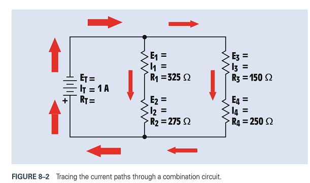
Refer to the circuit shown in Figure 8-2. Redraw the circuit and use the following values:
Assume that an ammeter indicates a total circuit current of 15 mA.
A voltmeter indicates the following voltage drops across each resistor:
What is the most likely problem with this circuit?

Trending nowThis is a popular solution!

Chapter 8 Solutions
Delmar's Standard Textbook Of Electricity


- ET E1 E2 E3 E41.248V IT I1 I2 I3 I4 RT R1 R2 R3 R4 PT0.576W P10.0806W P20.0461W P30.00184W P4 E5 E6 E7 E8 E9 I5 I6 I7 I8 I9 R5 R6 R7 R8 R9 P50.0203W P60.00995W P70.0518W P80.0726W P90.288W FIGURE 8-26 A combination circuit.arrow_forwardRefer to Figure 8-21. Assume that the resistors have the following values: R1=150R2=120R3=47R4=220 Assume that an ohmmeter connected across the entire circuit indicates a value of 245 . Does this reading indicate that there is a problem with the circuit and, if so, what is the most likely problem? FIGURE 8-21 Series-parallel circuit.arrow_forwardReferto Figure 8-2. Replace the values shown with the following. Solvefor all theunknownvalues. IT=0.6AR1=470R2=360R3=510R4=430arrow_forward
- 3. Find the unknown values in the circuit if the applied voltage is 18 V and the resistors have the following values: FIGURE 8-21 Series-parallel circuit.arrow_forwardRefer to the formulas in Appendix B in the Resistive-Capacitive Parallel Circuits section. A resistor and capacitor are connected in parallel to a 208-V, 60-Hz power source. An ammeter indicates a total circuit current of 46 amps, and a wattmeter indicates a true power of 4975 W. What is the resistance of the circuit?arrow_forwardThe circuit shows a variable resistor, with a lamp (L) connected to an ammeter and a voltmeter. By inspection, the circuit shown demonstrates that a) the variable resistor and voltmeter should be interchanged b) the lamp L and voltmeter should be interchanged c) the ammeter should be parallel with R, not with the lamp L d) the voltmeter and ammeter should be interchangedarrow_forward
- 8. A circuit consists of five unequal loads connected in parallel. To measure the resistance through one specific load, you must A. remove power from the circuit and measure the load's resistance in its installed location B. apply power to the circuit, disconnect the load from the circuit, and measure the load's resistance. C. apply power to the circuit, measure the overall circuit resistance, and divide this value by five. D. remove power from the circuit, disconnect the load from the circuit, and measure the load's resistance.arrow_forwardApply nodal analysis to find io and the power dissipated in each resistor in the circuit.arrow_forwardCalculate current through individual resistors in the following circuit diagram. (10 points) (Hint: Use nodal analysis techniques for easier solutionarrow_forward
- Calculate the short circuit current is the 5 ohm resistor is the load resistance. Show complete solution.arrow_forwardFor the given circuit below Replace RL with the calculated resistance RLmin which is 168.75 Ohms. Measure and calculate the following values: VL, IRs and IZ.arrow_forward024. A voltmeter of (0- 300V) and Ammeter of (0- 20A) are connected in a circuit to measure the value of power input to the circuit. Both the meters are found with a limiting error of 1.1% on half-scale deflection. Calculate the following, when the voltmeter and ammeter shows 230 V and 10 A respectively. i. ii. Limiting eror voltage Limiting error powerarrow_forward
 Delmar's Standard Textbook Of ElectricityElectrical EngineeringISBN:9781337900348Author:Stephen L. HermanPublisher:Cengage Learning