
Electric Circuits Fundamentals & Lab Mnl Pk
8th Edition
ISBN: 9780136125136
Author: Unknown
Publisher: PEARSON
expand_more
expand_more
format_list_bulleted
Concept explainers
Videos
Textbook Question
Chapter 8, Problem 50P
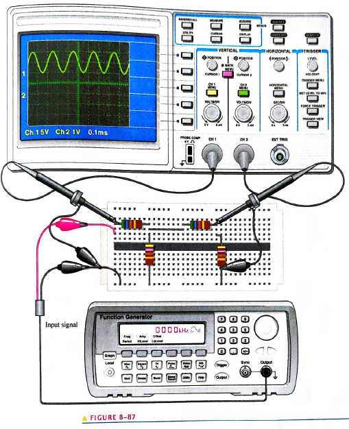
Based on the instrument settings and an examination of the scope display and the circuit board in Figure 8-87 determine the frequcncy and peak value of the input signal and output signal. The waveform shown is channel. Draw the channel 2 waveform as it would appear on the scope with the indicated scttings.
Expert Solution & Answer
Want to see the full answer?
Check out a sample textbook solution
Students have asked these similar questions
Determine the output voltage waveform for each circuit
Chose the correct answer
9- What is the modulating signal voltage if the maximum and the minimum voltages on the wave were observed to be 5.9v and 1.2v respectively?
a) 2.35v
b) 2.12v
c) 1.85v
d) 3.21v
Measure and record the peak-to-peak voltage across each of the following points in the table
Chapter 8 Solutions
Electric Circuits Fundamentals & Lab Mnl Pk
Ch. 8 - The period of a 60 Hz sine wave is 16.7 ms.Ch. 8 - The rms and average value of a sine wave are the...Ch. 8 - Prob. 3TFQCh. 8 - The peak value of a sine wave is the same as its...Ch. 8 - The number of radians in 360 is 2 .Ch. 8 - In a three-phase electrical system, the phases are...Ch. 8 - The purpose of an exciter is to supply dc rotor...Ch. 8 - In an automotive alternator, the output current is...Ch. 8 - Prob. 9TFQCh. 8 - A synchronous motor can be used when constant...
Ch. 8 - Prob. 1STCh. 8 - During each cycle, a sine wave reaches a peak...Ch. 8 - A sine wave with a frequency of 12 kHz is changing...Ch. 8 - Prob. 4STCh. 8 - When a sine wave has a frequency of 60 Hz, in 10 s...Ch. 8 - Prob. 6STCh. 8 - Prob. 7STCh. 8 - The average value of a 10 V peak sine wave over...Ch. 8 - Prob. 9STCh. 8 - Prob. 10STCh. 8 - The instantaneous value of a 15 A peak sine wave...Ch. 8 - If the rms curren through a 10k resistor is 5 m A,...Ch. 8 - Prob. 13STCh. 8 - Prob. 14STCh. 8 - Prob. 15STCh. 8 - Prob. 16STCh. 8 - Prob. 17STCh. 8 - Prob. 1TSCCh. 8 - Prob. 2TSCCh. 8 - Prob. 3TSCCh. 8 - Prob. 4TSCCh. 8 - Prob. 5TSCCh. 8 - Calculate the frequency for each of the following...Ch. 8 - Calculate the period for each of the following...Ch. 8 - A sine wave goes through 5 cycles in 10s. What is...Ch. 8 - A sine wave has a frequency of 50 kHz. How many...Ch. 8 - How long does it take a 10 kHz sine wave to...Ch. 8 - A sine wave has a peak value of 12 V. Determine...Ch. 8 - A sinusoidal current has an rms value of 5 mA....Ch. 8 - For the sine wave in Figure 8-74, determine the...Ch. 8 - If each horizontal division in Figure 8-74 is 1...Ch. 8 - In Figure 8-74, what is the instantaneous voltage...Ch. 8 - Sine wave A has a positive-going zero crossing at...Ch. 8 - One sine wave has a positive peak at 75 and...Ch. 8 - Draw two since waves as follows: Sline wave A is...Ch. 8 - Convert the following angular values from degrees...Ch. 8 - Convert the following angular values from radians...Ch. 8 - A certain sine wave has a positive-going zero...Ch. 8 - For a particular 0 reference sinusoidal current,...Ch. 8 - For a 0 reference sinw wave with an rms value of...Ch. 8 - Sine wave A lags sine wave B by 30. Both have peak...Ch. 8 - Repeat Problem 19 for the case when sine wave A...Ch. 8 - A sinusoidal voltage is applied to the resistive...Ch. 8 - Find the half-cycle average values of the voltages...Ch. 8 - Determine th rms voltage across R3 in Figure 8-77.Ch. 8 - A sine wave with an rms value of 10.6 V is riding...Ch. 8 - How much dc voltage must be added to a 3 V rms...Ch. 8 - A 6 V peak sine wave is riding on a dc voltage of...Ch. 8 - The conductive wire loop on the rotor of a simple...Ch. 8 - Prob. 28PCh. 8 - At what speed of rotation must a four-pole...Ch. 8 - A common frequency for alternators on aircraft is...Ch. 8 - Prob. 31PCh. 8 - Explain how the field in a three-phase motor...Ch. 8 - From the graph in Figure 8-78, determine the...Ch. 8 - Determine the duty cycle for each pulse waveform...Ch. 8 - Find the average value of each positive-going...Ch. 8 - What is the frequency of each waveform in Figure...Ch. 8 - What is the frequency of each sawtooth waveform in...Ch. 8 - A square wave has a period of 40s. List the first...Ch. 8 - What is the fundamental frequency of the square...Ch. 8 - Determine the peak value and the period of the...Ch. 8 - Determine the rms value and the frequency of the...Ch. 8 - Determine the rms value and the frequency of the...Ch. 8 - Find the amplitude, pulse width, and duty cycle...Ch. 8 - A certain sine wave has a frequency of 2.2 kHz and...Ch. 8 - Figure 8-84 shows a sinusoidal voltage source in...Ch. 8 - A nonsinusoidal waveform called a stairstep is...Ch. 8 - Refer to the oscilloscope screen in Figure 8-86....Ch. 8 - Accurately draw on a grid representing the scope...Ch. 8 - Accurately draw on a grid representing the scope...Ch. 8 - Based on the instrument settings and an...Ch. 8 - Examine the circuit board and the oscilloscope...Ch. 8 - Prob. 52PCh. 8 - www. prenhall.com/floyd. 53. Open file P08-53 and...Ch. 8 - www. prenhall.com/floyd. 54. Open file P08-54 and...Ch. 8 - www. prenhall.com/floyd. 55. Open file P08-55 and...Ch. 8 - www. prenhall.com/floyd. 56. Open file P08-56 and...
Knowledge Booster


Learn more about
Need a deep-dive on the concept behind this application? Look no further. Learn more about this topic, electrical-engineering and related others by exploring similar questions and additional content below.Similar questions
- Suppose you have a 100MHz clock and five LEDs. Design a circuit which turns each and only one LED on every second in the following order: LEDO, LED1, LED2, LED3, LEDA, LEDO, LED, LED2,-, so on.arrow_forward8: Draw the circuit diagram and the output waveform of a Zero Crossing Detector if the input is sinusoidalarrow_forwardDetermine the peak secondary voltagearrow_forward
- In proteus 8, Determine the voltages from the output of the three op-amps using an oscilloscope.arrow_forwarddraw the output voltage waveformarrow_forwardDetermine the output voltage waveform. Indicate the peak values (up to 2 significant decimal places) during the positive and negative half cycles. No need to indicate the sign.arrow_forward
- Draw the waveform of the given clipper circuit and determine the following: a.) At 0V, what is the output voltage?b.) At +20V, what is the output voltage?c.) At -5V, what is the output voltage?arrow_forwarda) (i) Draw the electrical model of a piezoelectric crystal. (ii) Over what portionof the reactance curve do we desire oscillations to take place when the crystal isused as part of a sinusoidal oscillator? Explain. b) An N-channel JFET has IDSS = 16 mA and VP= -6 volts. Calculate the draincurrent and VDS (sat) when VGS = -4 volts.arrow_forward1.Is it possible to change time period of the waveform withoutchanging R & C? 2.Discuss the advantage and disadvantage of linear voltage regulator 3.Give four applications of voltage regulatorsarrow_forward
arrow_back_ios
SEE MORE QUESTIONS
arrow_forward_ios
Recommended textbooks for you
 Delmar's Standard Textbook Of ElectricityElectrical EngineeringISBN:9781337900348Author:Stephen L. HermanPublisher:Cengage Learning
Delmar's Standard Textbook Of Electricity
Electrical Engineering
ISBN:9781337900348
Author:Stephen L. Herman
Publisher:Cengage Learning
Number Systems Introduction - Decimal, Binary, Octal & Hexadecimal; Author: The Organic Chemistry Tutor;https://www.youtube.com/watch?v=FFDMzbrEXaE;License: Standard Youtube License