
Videos
Positive-sequence components consist of three phasors _________ with magnitudes and _________ phase displacement in positive sequence; negative- sequence components consist of three phasors with ________ magnitudes and _________ phase displacement in negative sequence; and zero-sequence components consist of three phasors with __________ magnitudes and __________ phase displacement.
To fill: The appropriate words in the given blank spaces.
Answer to Problem 8.1MCQ
The appropriate words are: equal,
Explanation of Solution
The method of symmetrical components is used to solve the unbalanced system. This method is also termed as three-component method. The balanced set of components are positive sequence component, negative sequence component and zero-sequence component.
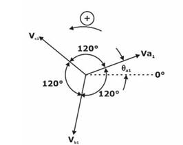
Positive Sequence components: The positive-sequence system is represented by a balanced system of phasors having the same phase sequence (and therefore positive phase rotation) as the original unbalanced system. The phasors of the positive-sequence system are equal in magnitude and displaced from each other by
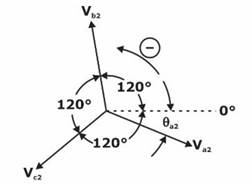
Negative Sequence components: The negative-sequence system is represented by a balanced system of phasors having the opposite phase sequence (and therefore negative phase rotation) to the original system. The phasors of the negative-sequence system are also equal in magnitude and displaced from each other by
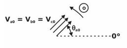
Zero Sequence components: The zero-sequence system is represented by three single phasors that are equal in magnitude and angular displacement between all the phasors is
Therefore, in positive-sequence component, there are three phasors of equal magnitude but
Want to see more full solutions like this?
Chapter 8 Solutions
Power System Analysis and Design (MindTap Course List)


- Equipment ratings for the five-bus power system shown in Figure 7.15 are as follows: Generator G1:    50 MVA, 12kV, X=0.2 per unit Generator G2: 100 MVA, 15 kV, X=0.2 per unit Transformer T1: 50 MVA, 10 kV Y/138kVY,X=0.10 per unit Transformer T2: 100 MVA, 15 kV /138kVY,X=0.10 per unit Each 138-kV line: X1=40 A three-phase short circuit occurs at bus 5, where the prefault voltage is 15 kV. Prefault load current is neglected. (a) Draw the positive-sequence reactance diagram in unit on a 100-MVA, 15-kV base in the zone of generator G2. Determine (b) the Thévenin equivalent at the fault, (c) the subtransient fault current in per unit and in kA rms, and (d) contributions to the fault from generator G2 and from transformer T2.arrow_forwardEquipment ratings for the four-bus power system shown in Figure 7.14 are as follows: Generator G1: 500 MVA, 13.8 kV, X=0.20 per unit Generator G2: 750 MVA, 18 kV, X=0.18 per unit Generator G3: 1000 MVA, 20 kV, X=0.17 per unit Transformer T1: 500 MVA, 13.8/500YkV,X=0.12 per unit Transformer T2: 750 MVA, 18/500YkV,X=0.10 per unit Transformer T3: 1000 MVA, 20/500YkV,X=0.10 per unit A three-phase short circuit occurs at bus 1, where the prefault voltage is 525 kV. Prefault load current is neglected. Draw the positive-sequence reactance diagram in per unit on a 1000-MVA, 20-kV base in the zone of generator G3. Determine (a) the Thévenin reactance in per unit at the fault, (b) the subtransient fault current in per unit and in kA rms, and (c) contributions to the fault current from generator G1 and from line 1-2.arrow_forward
 Power System Analysis and Design (MindTap Course ...Electrical EngineeringISBN:9781305632134Author:J. Duncan Glover, Thomas Overbye, Mulukutla S. SarmaPublisher:Cengage Learning