
(a)
The design of a four-bolt unstiffened end-plate connection for a
Answer to Problem 8.8.3P
9/16-in. fillet weld at each flange.
¼-in. fillet weld on each side of the web in the tension region.
½-in. fillet weld on each side of the web between mid-depth and the compression flange.
Explanation of Solution
Given:
A992 steel for members
A36 steel for the end plate
Group A pretensioned bolts
Formula used:
Calculation:
From the
From the dimensions and properties tables
Workable gauge = 3.50 in.
For the bolt pitch, try
For the gauge distance, use the workable gauge g = 3.50 in.
Required bolt diameter:
Try
Moment strength based on bolt strength:
Therefore, use
Determine end-plate width:
Minimum
The minimum plate width is
Maximum effective end-plate width =
Try
Determine the required plate thickness:
Therefore, use the original value of
Required
Try
Beam flange force:
The shear yield strength of the end plate is
Shear rupture strength of end plate:
Check bolt shear:
The compression side bolts must be capable of resisting the entire vertical shear.
For 4 bolts,
Try
For 4 bolts,
Recompute the plate dimensions:
For
Minimum
The minimum plate width is
Maximum effective end-plate width =
Use the currently selected width of
Because the bolt size has increased, check the shear rupture strength of the end plate:
Check bearing in the plate at the compression side bolts.
For the outer bolts,
The upper limit is
Therefore, use
Since the inner bolts are not near an edge or adjacent bolts, the outer bolts control.
The total bearing strength is
Check bearing in the column flange:
Use
The upper limit is
Therefore, use
The total bearing strength is
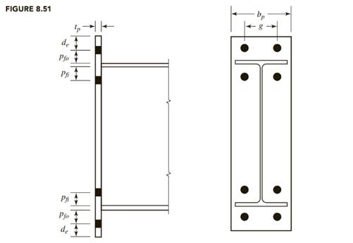
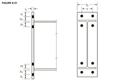
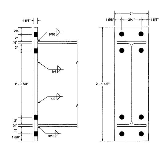
The plate length, using detailing dimensions and the notation of figure given below from the textbook (Steel design), is
Use a
Beam flange to plate weld design:
The flange force is
AISC Design Guide 4 recommends that the minimum design flange force should be 60% of the flange yield strength:
Minimum
Therefore, use the actual flange force of 203.1 kips.
The flange weld length is
The weld strength is
where D is the weld size in sixteenths of an inch and the factor of 1.5 accounts for the direction of the load on the weld. If we equate the weld strength to the flange force,
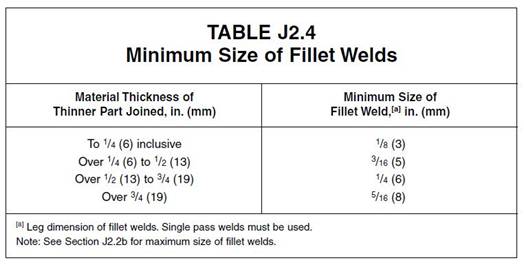
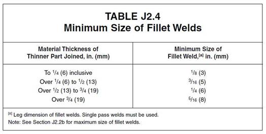
From AISC Table J2.4, the minimum weld size is ¼-in. (based on the thickness of the flange, which is the thinner connected part).
Use a 9/16-in. fillet weld at each flange.
Beam web to plate weld design:
To develop the yield stress in the web near the tension bolts, let
Use a ¼-in. fillet weld on each side of the web in the tension region.
The applied shear of
- From the mid-depth to the compression flange.
From the inner row of tension bolts plus
- to the compression flange:
Equating the weld strength to the required shear strengths, we get
From AISC Table J2.4, the minimum weld size is 3/16-in.
Use a ½-in. fillet weld on each side of the web between mid-depth and the compression flange.
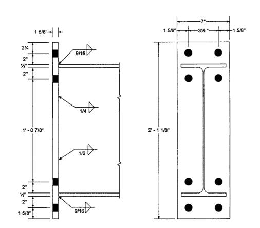
The design is summarized in the figure below:
Conclusion:
Use a
(b)
The design of a four-bolt unstiffened end-plate connection for a
Answer to Problem 8.8.3P
9/16-in. fillet weld at each flange.
¼-in. fillet weld on each side of the web in the tension region
½-in. fillet weld on each side of the web between mid-depth and the compression flange.
Explanation of Solution
Given:
A992 steel for members
A36 steel for the end plate
Group A pretensioned bolts
Formula used:
Calculation:
From the
From the dimensions and properties tables
Workable gauge = 3.50 in.
For the bolt pitch, try
For the gauge distance, use the workable gauge g = 3.50 in.
Required bolt diameter:
Try
Moment strength based on bolt strength:
Therefore, use
Determine end-plate width:
Minimum
The minimum plate width is
Maximum effective end-plate width =
Try
Determine the required plate thickness:
Therefore, use the original value of
Required
Try
Beam flange force:
The shear yield strength of the end plate is
Shear rupture strength of end plate:
Check bolt shear:
The compression side bolts must be capable of resisting the entire vertical shear.
For 4 bolts,
Try
For 4 bolts,
Recompute the plate dimensions:
For
Minimum
The minimum plate width is
Maximum effective end-plate width =
Use the currently selected width of
Because the bolt size has increased, check the shear rupture strength of the end plate:
Check bearing in the plate at the compression side bolts.
For the outer bolts,
The upper limit is
Therefore, use
Since the inner bolts are not near an edge or adjacent bolts, the outer bolts control.
The total bearing strength is
Check bearing in the column flange:
Use
The upper limit is
Therefore, use
The total bearing strength is
The plate length, using detailing dimensions and the notation of figure given below from the textbook, is
Use a
Beam flange to plate weld design:
The flange force is
AISC Design Guide 4 recommends that the minimum design flange force should be 60% of the flange yield strength:
Minimum
Therefore, use the actual flange force of 135.4 kips.
The flange weld length is
The weld strength is
where D is the weld size in sixteenths of an inch and the factor of 1.5 accounts for the direction of the load on the weld. If we equate the weld strength to the flange force,
From AISC Table J2.4, the minimum weld size is ¼-in. (based on the thickness of the flange, which is the thinner connected part).
Use a 9/16-in. fillet weld at each flange.
Beam web to plate weld design:
To develop the yield stress in the web near the tension bolts, let
Use a ¼-in. fillet weld on each side of the web in the tension region.
The applied shear of
- From the mid-depth to the compression flange.
From the inner row of tension bolts plus
- to the compression flange:
Equating the weld strength to the required shear strengths, we get
From AISC Table J2.4, the minimum weld size is 3/16-in.
Use a ½-in. fillet weld on each side of the web between mid-depth and the compression flange.
The design is summarized in the figure below:
Conclusion:
Use a
Want to see more full solutions like this?
Chapter 8 Solutions
Steel Design (Activate Learning with these NEW titles from Engineering!)

 Steel Design (Activate Learning with these NEW ti...Civil EngineeringISBN:9781337094740Author:Segui, William T.Publisher:Cengage Learning