Concept explainers
Videos
The resistance of loop 2 is greater than that loop l. (The loop are made from different materials.)
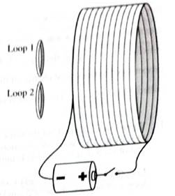
1. Is there a current induced through the wire of either of the loops:
• before the switch is closed? Explain.
• just after the switch is closed? Explain.
• a long after the switch is closed? Explain.
2. For the period of time that there is a current included through the wire of the loops, find the direction of the current.
3. The ratio of the induced currents for the two loops is found by experiment to be equal to the inverse of the ratio of the resistances of the loops.
What does this observation imply about the ratio of the induced emf in loop 1 to the induced emf in loop 2?
(1)
To Identify:
Induced current through wire of the loops as per the given conditions:
- Before the switch is closed.
- After when the switch is closed.
- After a long-time when the switch is closed.
Explanation of Solution
Introduction:
According to Faradays’ law, an e.m.f is induced in a loop of wire if there is a rate of change in flux passing through the wire.
Where,
Case1: Before the switch is closed:
Before the switch is closed, there is no current flowing in solenoid (bigger loop) that can produce changing magnetic field. Hence, there is no change in flux in the small loops. Therefore, there is no induced current in small coils.
Case 2: After the switch gets closed:
Just after the switch is closed, the current in the solenoid (bigger loop) goes from zero to maximum which makes the magnetic field lines passing through the small loops change. Hence, due to change in flux, there will be induced current in them. The loop with higher resistance will be associated with less induced current.
Case 3: After longtimewhen the switch isclosed:
After long time the switch is closed, there is constant current in solenoid (bigger loop) that produces constant magnetic field. Hence, there is no change in flux in the small loops. Therefore, there is no current in small loops.
Conclusion:
Therefore, following Faraday’s law, there is an induced current in small coils just when switch is closed and is zero for other cases.
(2)
To Find
The direction current induced through a wire of the loops.
Explanation of Solution
Introduction:
According to Lenz’s law, the induced emf will form a magnetic field which counteracts the change in flux.
By seeing the sign of the battery (current flows from positive to negative terminal) and using the right-hand rule, the direction of magnetic field induced in the greater loop must be from left to right. When switch is closed, then the induced current in small loop is in such a way that decreases the magnetic flux produced by the larger loop, hence, the induced current is in clockwise while seeing the loop from right. When switch is opened, the induced current will flow in anticlockwise direction.
Conclusion:
Therefore, the current induced through a wire of the loop will be such that it will oppose the change in flux produced by the bigger loop.
(3)
To Explain:
The ratio of induced emf in the loop 1to the loop 2.
Answer to Problem 1aT
Ratio of emf induced in loop 1to loop 2 is equal.
Explanation of Solution
Introduction:
According to Faradays’ law, an e.m.f is induced in a loop of wire if there is a rate of change in flux passing through the wire.
Where,
The induced emf depends on the rate of change in flux. Considering the area of the small loops same, the change in magnetic flux will be same for both the loops. Therefore, the induced emf will be same.
The induced current will be different in both the loops though, as the resistance of the loop 2 is greater than the loop 1.
Conclusion:
Therefore, induced emf will be same in both smaller loops.
Want to see more full solutions like this?
Chapter 8 Solutions
Tutorials In Introductory Physics: Homework
Additional Science Textbook Solutions
College Physics (10th Edition)
Physics for Scientists and Engineers: A Strategic Approach, Vol. 1 (Chs 1-21) (4th Edition)
Physics for Scientists and Engineers with Modern Physics
University Physics Volume 2
University Physics (14th Edition)
Essential University Physics (3rd Edition)


- Additional Problems Two circular loop of wire surround an insulating rod as in Figure P20.53. Loop I carries a current I in the clockwise direction when viewed from the left end. If loop I moves toward loop 2, which remains stationary, what is the direction of the induced current in loop 2 when slewed from the left end? Figure P20.53arrow_forwardReferring to Figure 23.58, what are the directions of the currents in coils 1, 2, and 3 (assume that the coils are lying in the plane of the circuit): (a) When the switch is first closed? (b) When the switch has been closed for a long time? (c) Just after the switch is opened?arrow_forwardPLS ANSWER WITHIN 15 MINSarrow_forward
- Please help asaparrow_forwardItem 1 The lightbulb in the circuit shown in the figure(Figure 1) has a resistance of 102 and consumes 9.7 W of power; the rod is 1.17 m long and moves to the left with a constant speed. The strength of the magnetic field is 2.3 T. Figure R O, O O O O O O O external magnetic 1 of 1 Part A Find the current in the circuit. Express your answer using two significant figures. ▸ View Available Hint(s) VE ΑΣΦΑ I = Submit Part B Find the speed of the rod. Express your answer using two significant figures. ► View Available Hint(s) 17| ΑΣΦ V = Submit Provide Feedback 2 ? ? A m/sarrow_forward1.How does the looped conductor with the current I behave in the field B? Explain your answer. Note: The diagram shows the direction of a conventional current.arrow_forward
- 2- Solve a-) with explainarrow_forwardPart A Faraday's law of induction deals with how a changing magnetic flux induces an emf in a circuit. Recall that magnetic flux depends on magnetic field strength and the effective area the field is passing through. We'll start our investigation by looking at the field strength around a bar magnet. Position the magnet around the coil so that the region labeled A in the figure below is inside the coil. Move the magnet slowly back and forth and observe the effect on the brightness of the bulb and the needle of the voltmeter. Repeat the same process for the other two regions. For which of the regions shown in the figure is the observed effect the strongest? OO оо Re C Region B The observed effect is the same for all three regions. Region A A Submit Request Answer N S B сarrow_forwardPart A Faraday's law of induction deals with how a changing magnetic flux induces an emf in a circuit. Recall that magnetic flux depends on magnetic field strength and the effective area the field is passing through. We'll start our investigation by looking at the field strength around a bar magnet. Position the magnet around the coil so that the region labeled A in the figure below is inside the coil. Move the magnet slowly back and forth and observe the effect on the brightness of the bulb and the needle of the voltmeter. Repeat the same process for the other two regions. For which of the regions shown in the figure is the observed effect the strongest? Region C The observed effect is the same for all three regions. O Region A O Region B Submit Request Answer A N S B Carrow_forward
- R2 R1 Consider the circuit shown in the figure. Suppose that the switch has been open for a very long time. The switch is then closed. When is the current in R2 zero? O Immediately after closing the switch. A very long time after closing the switch. O The current in R2 is never zero. Not enough information is given. O One time constant after closing the switch.arrow_forwardConsider the schematic diagram below. What is the direction of the loop? a. Counterclockwiseb. Clockwisec. Cannot be determinedarrow_forwardPart A A step-up transformer increases 10 V to 150 V . What is the current in the secondary coil as compared to the primary coil? Assume 100% efficiency. Express your answer using two significant figures. ? %3Darrow_forward
 College PhysicsPhysicsISBN:9781285737027Author:Raymond A. Serway, Chris VuillePublisher:Cengage Learning
 College PhysicsPhysicsISBN:9781305952300Author:Raymond A. Serway, Chris VuillePublisher:Cengage Learning
 Principles of Physics: A Calculus-Based TextPhysicsISBN:9781133104261Author:Raymond A. Serway, John W. JewettPublisher:Cengage Learning
 Physics for Scientists and EngineersPhysicsISBN:9781337553278Author:Raymond A. Serway, John W. JewettPublisher:Cengage Learning
 Physics for Scientists and Engineers with Modern ...PhysicsISBN:9781337553292Author:Raymond A. Serway, John W. JewettPublisher:Cengage Learning
 Physics for Scientists and Engineers, Technology ...PhysicsISBN:9781305116399Author:Raymond A. Serway, John W. JewettPublisher:Cengage Learning