
Concept explainers
The unknown parameters using Kirchhoff’s Laws.
Answer to Problem 1PP
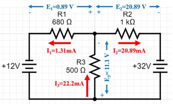
| ES1= 12 V | E1= 0.89 V | E2= 20.89 V | E3= 11.1 V |
| ES2= 32 V | I1= 1.31 mA | I2= 20.89 mA | I3= 22.2 mA |
| R1= 680 Ω | R2=1000 Ω | R3=500 Ω |
Explanation of Solution
We will use Kirchhoff’s Voltage law to solve for the unknown parameters.
Consider two loops LOOP 1 and LOOP 2 with their respective loop currents I1 and I2
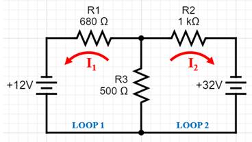
Using KVL in loop 1,
Using KVL in loop 2,
From equation (1), we can write I2as ,
Substitute this expression for I2in equation (2),
Substitute the value of I1 in equation (3).
CurrentI3 is the sum of currents I1 and I2
The voltage drops are obtained by using Ohm’s Law,
The results are summarized in the figure below,
Want to see more full solutions like this?
Chapter 9 Solutions
DELMAR'S STANDARD TEXT OF ELECTRICITY


- 17- The electromechanical breakdown depend on the type of the dielectric between two electrodes a- Right. b- Wrong 18- Basic Insulation Level (BIL) is related to the design consideration of the electric device, while Basic protection (BPL) level is related to protection level of the that device. a Right. Wrong. b- 19- As the voltage regulation increased, receiving end voltage will be reduced. Right. b- Wrong 20- We can be using Solar power generation field as a power factor and voltage profile enhancement in Distribution system. (aRight. b- Wrong. 21- From the general electrostatic theories, the field strength at breakdown is given by: a Eb = V/ do =0.6 [Y/ (€ o Er) ] 0.5. b- Eb V/ do = 0.6 [Y / (€ 0/Er )] 0.5. C- Eb V/ do = 0.6 [ Y/(Eo Er) 20.05. d- Eb V/ do = 0.6 [ Y/ (Eo Er) 10.5. 22- Consider plane electrodes with a solid insulator between them. Find the electric field strength at breakdown, if Young's modulus = 10000 (V.F/m2). and the relative permittivity is (36000 TT). If the…arrow_forwardComplex power S in (VA) S=______________ Power P in Watts P=______________ Reactive Power Q (VAR) Q=______________arrow_forward5arrow_forward
- A Moving to another question will save this response. Question 4 What is the approximate value of surge impedance of a power cable ? 400 100 40 1600 A Moving to another question will save this response.arrow_forwardThe following are the correct sign conventions for analyzing circuits using Kirchhoff's Laws EXCEPT: For travel direction from negative to positive terminal, the emf should be positive. For travel direction from positive to negative terminal, the emf should be negative. For travel direction opposite to current direction, the voltage drop across the resistor should be negative. For travel direction same as the current direction, the voltage drop across the resistor should be negative.arrow_forwardWhen a breadboard is oriented horizontally, the top positive RED rail is electrically connected to the bottom positive RED rail. A) True B Falsearrow_forward
- Question 6: 1- List the pins on Arduino that can do analog write. 2- In a PWM, given that the duty cycle is 80% what is the voltage output? 3- In a PWM, what should be the duty cycle to get a voltage output of 4.5 V? 4- Given the bellow Arduino command: analogWritel 8, 200); a- What is the duty cycle? b- What is the voltage output?arrow_forwardIn which of the following wind energy conversion system, guy wire may be required? O a. Vertical axis wind turbines Ob. Horizontal axis wind turbines O c. Up wind turbines O d. Down wind turbinesarrow_forwardVdc0 U=12 V Circuit #1 Ried V LED www Ried_series 0.05 Vdc0 U = 12 V 0,04 Circuit 0.03 0.02 0.01 RED LED GREEN LE Set current to 10 mA LED voltages Given the circuit #1 presented above, answer the following questions: BLUE_LEC Red 0.5 1) Determine the value of the V₁ (voltage forward of the LED) for the LEDS RED, VDRED GREEN, VREEN and BLUE, VOBLUES when the current through the LEDs is 10mA, 2) Is the LED in Circuit #1, connected in the way that will be lighting up or not - Justify your answer Green 3) Calculate the value of the resistance Rled in Circuit #1, to ensure that a RED LED will have a current of 10 mA 1.5 2 25 Voltage across LED (V) 4) Calculate the value of the resistance Rled in Circuit #1, to ensure that a GREEN LED will have a current of 10 mA Blue 5) Calculate the value of the resistance Rled in Circuit #1, to ensure that a Blue LED will have a current of 10 mA 6) Given three LEDs, connected in series as shown in the Circui # 2 (below), calculate the value of the…arrow_forward
- i need the answer quicklyarrow_forwardE2(V) 120V Test Open-circuit Short- circuit Primary 12(A) .29A 2A P2(W) 8.78W 13.4W 6.85V E1(V) P1(W) 7.69W 13.14W Test Open-circuit Short- circuit 11(A) .62A SA 48V 2.83V Normal 12 at E1 11 P1 E2 12 P2 120V 50.6V 48.42V 48.8V 49.33V 182A 4A 6A 815A 1A 1.22A 142A .2 4.75A 237.4W 56.5W 120.3V 1.31A 1.77A 2.28A 2.73A 3.26А 3.74A 119.6V 119.8V 120.6V 119.4V 120.6V 120.1V 119.9V 120.3V 219.1W 48.3W 72.39W 98.3W 120.1W 146.9W .4 81.2W 108.2W 130.5W 159.2W 184W 209.2W 237.5W .8 49.1V 1.2 1.4 49.83V 49.91V 50.1V 50.55V 170W 193.6W 219.1W 238.1W 1.6 4.23A 1.616A 1.8 4.74A 1.82A 2.0 50.3V 5.18A 258.3W 119.1V 2A 1) Calculate the turns ratio from the transformer primary/secondary voltage ratinga a= Using the open-circuit data at the primary and the short-circuit data at the secondary, calculate the four transformer parameters (to 3 significant figures) and fill in the following table. Parameter Rel Value(ohm) Xel Rc1 Xm1 Using the open-circuit data at the secondary and the short-circuit data at…arrow_forwardQuestion 6: 1- List the pins on Arduino that can do analog write. 2- In a PWM, given that the duty cycle is 80% what is the voltage output? 3- In a PWM, what should be the duty cycle to get a voltage output of 4.5 V? 4- Given the bellow Arduino command: analogWrite( 8, 200); a- What is the duty cycle? b- What is the voltage output?arrow_forward
 EBK ELECTRICAL WIRING RESIDENTIALElectrical EngineeringISBN:9781337516549Author:SimmonsPublisher:CENGAGE LEARNING - CONSIGNMENT
 Electricity for Refrigeration, Heating, and Air C...Mechanical EngineeringISBN:9781337399128Author:Russell E. SmithPublisher:Cengage Learning
 Power System Analysis and Design (MindTap Course ...Electrical EngineeringISBN:9781305632134Author:J. Duncan Glover, Thomas Overbye, Mulukutla S. SarmaPublisher:Cengage Learning