
Videos
For the circuit of Fig. 9.45, is(t) = 30u(−t) mA. (a) Select R1 so that v(0+) = 6 V. (b) Compute v(2 ms). (c) Determine the settling time of the capacitor voltage. (d) Is the inductor current settling time the same as your answer to part (c)?
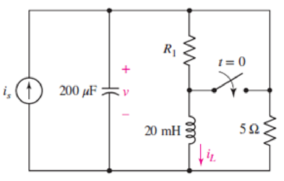
FIGURE 9.45
(a)
Select
Answer to Problem 26E
The resistance
Explanation of Solution
Given Data:
Formula used:
The expression for the exponential damping coefficient or the neper frequency is as follows:
Here,
The expression for the resonant frequency is as follows:
Here,
The expression for a critically damped response of a source free parallel RLC circuit is as follows:
Here,
Calculation:
The unit-step forcing function as a function of time which is zero for all values of its argument less than zero and which is unity for all positive values of its argument.
Here,
So, at
The redrawn circuit diagram is given in Figure 1 at
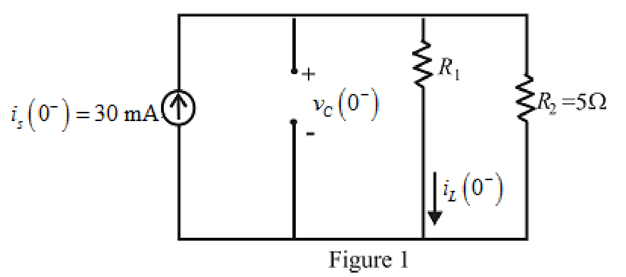
Refer to the redrawn Figure 1:
The expression for the current through the inductor at
Here,
The expression for the voltage across the capacitor at
Here,
Substitute
The capacitor does not allow sudden change in the voltage, so,
The voltage across the capacitor at
Substitute
Rearrange for
The resistance cannot be negative so, the resistance
Conclusion:
Thus, the resistance
(b)
Compute
Answer to Problem 26E
The value of the voltage
Explanation of Solution
Given data:
The time is
Calculation:
Substitute
The inductor does not allow sudden change in the current.
So,
So the current through inductor at
The redrawn circuit diagram is given in Figure 2 at
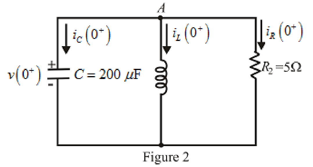
Refer to the redrawn Figure 2:
The expression for the current flowing in the
Here,
Substitute
Apply KCL at node
Here,
Substitute
Rearrange for
Substitute
Substitute
Substitute
Substitute
The voltage across the capacitor at
Substitute
Rearrange for
The expression for the current flowing through the
Substitute
Rearrange for
Substitute
The current flowing through the
Substitute
Substitute
Rearrange for
Substitute
Substitute
Conclusion:
Thus, the value of the voltage
(c)
Determine the settling time of the capacitor voltage.
Answer to Problem 26E
The settling time of the capacitor voltage is
Explanation of Solution
Calculation:
The maximum voltage appears across the capacitor at
So, for maximum voltage,
Substitute
Settling time is the time at which the value of the voltage reaches
The expression for the voltage at
Here,
Substitute
Substitute
The value of
Conclusion:
Thus, the settling time of the capacitor voltage is
(d)
Is the inductor current settling time the same as your answer to part (c)?
Answer to Problem 26E
The inductor current settling time is not same as capacitor voltage settling time.
Explanation of Solution
Calculation:
The expression for the current through inductor is as follows:
Here,
Substitute
Simplify further.
The maximum current through the inductor is at
So, for the maximum current,
Substitute
Settling time is the time at which the value of the current reaches
The expression for the current at
Here,
Substitute
Substitute
Rearrange equation (22).
The value of
So the inductor current settling time is
Conclusion:
Thus, the inductor current settling time is not same as capacitor settling time.
Want to see more full solutions like this?
Chapter 9 Solutions
Engineering Circuit Analysis


- Calculate initial conditions for inductor current and capacitor voltage in circuit presented in Fig. 8.3. Assume: L=1H, C=0.5F, R=1Ω, e(t) = 10 2 sin(t + 45 ) V, i(t) = 2sin(t − 45 ) A.arrow_forwardA series circuit has a capacitor of 1.5625x10^(-8)F a resistor of 2x10^4 ohms, and an inductor of 1H. If the initial charge on the capacitor is zero,. if a 12-volt battery is connected to the circuit and the circuit is closed at t=0, determine the charge on the capacitor at any time tarrow_forwardA resistor of 100 Ω, a coil of 4.50 μH, and a capacitor of 220 pF are in parallel. What is the admittance vector at 6.50 MHz? Provide illustration of the circuit.arrow_forward
- Calculate the current in an RLC circuit with resistances R=11 ohms, L=0.1 H, and C=10^-2 F that is linked to the source V(t)= 10sin 377t. Assume that the capacitor charge and current are both zero at time t=0.arrow_forwardA 20μF capacitor is subjected to a voltage pulse having a duration of 1 s. The pulse is described by the following equations: vc(t)={30t2 V,0≤t≤0.5 s;30(t−1)2 V,0.5 s≤t≤1 s;0elsewhere. Sketch the current pulse that exists in the capacitor during the 1 s interval.arrow_forwardA 200 Ω resistor, 0.900 H inductor, and 6.00 µF capacitor are connected in series across a voltage source that has voltage amplitude 30.0 V and an angular frequency of 250 rad/s. (a) What are v, vR, vL, and vC at t = 20.0 ms? Compare vR + vL + vC to v at this instant. (b) What are VR, VL, and VC? Compare V to VR + VL + VC. Explain why these two quantities are not equal.arrow_forward
- The current in a 20 mH inductor is known to be i=40 mA,t≤0; i=A1e−10,000t+A2e−40.000tA,t≥0. The voltage across the inductor (passive sign convention) is 28 V at t=0. 1. Find the expression for the voltage across the inductor for t>0. 2. Find the time, greater than zero, when the power at the terminals of the inductor is zero.arrow_forwardIn the series circuit of Fig, the source has voltage amplitude 20.0 V and angular frequency 5.40 x 10³ rad/s, the inductance is 6.50 mH, the capacitance is 0.600 µF, and the impedance is 474 Ω. Find (a) the resistance, (b) the current amplitude, (c) the resistor voltage amplitude, (d) the inductor voltage amplitude, and (e) the capacitor voltage amplitudearrow_forwardAn electrical circuit has a very small resistance so it can be despised. The capacitor on the left was charged up to the voltage of Vo=10 volts and then, at time t=0, the switch S was closed. The capacity of the capacitors are C=60 µF, and the coil inductance is L=0.04 HI) Find the voltage on the left capacitor, at the instant V1=0.001 s.II) Find the voltage in the right capacitor, at the instant t=002 s.arrow_forward
- For t < 0, the capacitor in the given figure is completely discharged. Assume that the switch is thrown at t = 0. Let VS = 15 V, R = 200 Ω, L = 20 mH, and C = 0.1 μF.arrow_forwarda series rlc circuit having values of pure resistance r=40 ohms and pure inductance l = 50.07 mh. the circuit draws 10 A of current when it is connected across a 400 v , 50hz ,ac supply. calculate the (1) capacitor value and (2) power factor of circuit.arrow_forwardA series LR circuit has a variable inductor with theinductance L(t) is defined by intervals.Find the current i(t) if the resistance is 0.2 ohms, the voltageapplied is E(t) = 4 volts; knowing that i(0) = 0.arrow_forward
 Introductory Circuit Analysis (13th Edition)Electrical EngineeringISBN:9780133923605Author:Robert L. BoylestadPublisher:PEARSON
 Delmar's Standard Textbook Of ElectricityElectrical EngineeringISBN:9781337900348Author:Stephen L. HermanPublisher:Cengage Learning
 Programmable Logic ControllersElectrical EngineeringISBN:9780073373843Author:Frank D. PetruzellaPublisher:McGraw-Hill Education
 Fundamentals of Electric CircuitsElectrical EngineeringISBN:9780078028229Author:Charles K Alexander, Matthew SadikuPublisher:McGraw-Hill Education
 Electric Circuits. (11th Edition)Electrical EngineeringISBN:9780134746968Author:James W. Nilsson, Susan RiedelPublisher:PEARSON
 Engineering ElectromagneticsElectrical EngineeringISBN:9780078028151Author:Hayt, William H. (william Hart), Jr, BUCK, John A.Publisher:Mcgraw-hill Education,