
Fundamentals Of Applied Electromagnetics
7th Edition
ISBN: 9781292082448
Author: Fawwaz T Ulaby Umberto Ravaioli
Publisher: Pearson Education Dorling Kindersley
expand_more
expand_more
format_list_bulleted
Concept explainers
Videos
Textbook Question
Chapter 9, Problem 26P
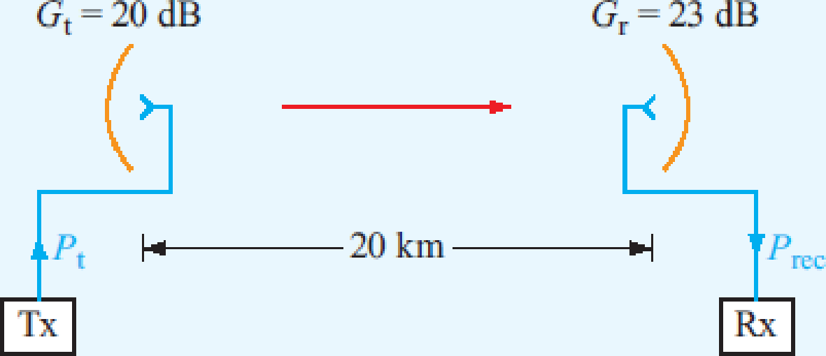
Consider the communication system shown in Fig. P9.26, with all components properly matched. If Pt = 10 W and f = 6 GHz:
- (a) What is the power density at the receiving antenna (assuming proper alignment of antennas)?
- (b) What is the received power?
- (c) If Tsys = 1,000 K and the receiver bandwidth is 20 MHz, what is the signal-to-noise ratio in decibels?
Figure P9.26 Communication system of Problem 9.26.
Expert Solution & Answer
Want to see the full answer?
Check out a sample textbook solution
Students have asked these similar questions
A transmitting base station antenna with an effective height of 100 m has a base current (rms) of 100 A at 300 kHz. What will be the electric field strength at a distance of 10 km?
2.) The power density is 4 mW/m² at some distance R from an isotropic antenna. The isotropic antenna is replaced with a different antenna and the power density measured is now 60 mW/m² at the same distance R. What is the gain (in dB) of the second antenna?
3.) The received power at an airplane is calculated as Pr=-43 dBm at a range of 13 miles using free-space propagation. Determine the received power (in dBm) at a range of 52 miles.
wireless communication
For an earth station receiver with an equivalent input temperature of 200 K, a noise bandwidthof 20 MHz, a receive antenna gain of 50 dB, and a carrier frequency of 12 GHz, determine thefollowing: G/Te, N0, and N.
Chapter 9 Solutions
Fundamentals Of Applied Electromagnetics
Ch. 9.1 - What does it mean to say that most antennas are...Ch. 9.1 - What is the radiated wave like in the far-field...Ch. 9.1 - In a Hertzian dipole, what is the underlying...Ch. 9.1 - Outline the basic steps used to relate the current...Ch. 9.1 - A 1 m long dipole is excited by a 5 MHz current...Ch. 9.2 - Prob. 5CQCh. 9.2 - What is the magnitude of the directivity of an...Ch. 9.2 - An antenna has a conical radiation pattern with a...Ch. 9.2 - Prob. 3ECh. 9.3 - What is the physical length of a half-wave dipole...
Ch. 9.3 - How does the radiation pattern of a half-wave...Ch. 9.3 - How does the radiation efficiency of a...Ch. 9.3 - Prob. 4ECh. 9.3 - Prob. 5ECh. 9.5 - Prob. 6ECh. 9.5 - At 100 MHz, the pattern solid angle of an antenna...Ch. 9.6 - If the operating frequency of the communication...Ch. 9.6 - Prob. 9ECh. 9.6 - Prob. 10ECh. 9.8 - Verify that Eq. (9.86) is a solution of Eq. (9.85)...Ch. 9.8 - Prob. 12ECh. 9.8 - What condition must be satisfied in order to use...Ch. 9.8 - Derive an expression for the array factor of a...Ch. 9.8 - Prob. 15ECh. 9.11 - Prob. 11CQCh. 9.11 - Prob. 12CQCh. 9.11 - Prob. 13CQCh. 9.11 - Prob. 14CQCh. 9.11 - Prob. 15CQCh. 9 - A center-fed Hertzian dipole is excited by a...Ch. 9 - A 50 cm long center-fed dipole directed along the...Ch. 9 - Prob. 3PCh. 9 - Determine the following: (a) The direction of...Ch. 9 - Repeat Problem 9.4 for an antenna with...Ch. 9 - A 2 m long center-fed dipole antenna operates in...Ch. 9 - Repeat Problem 9.6 for a 20 cm long antenna...Ch. 9 - Prob. 9PCh. 9 - An antenna with a radiation efficiency of 90% has...Ch. 9 - Prob. 11PCh. 9 - The normalized radiation intensity of a certain...Ch. 9 - Repeat Problem 9.6 for a 1 m long half-wave dipole...Ch. 9 - Prob. 14PCh. 9 - A 50 cm long dipole is excited by a sinusoidally...Ch. 9 - Prob. 16PCh. 9 - For a dipole antenna of length l = 3/2, (a)...Ch. 9 - Prob. 18PCh. 9 - Prob. 19PCh. 9 - Prob. 20PCh. 9 - A car antenna is a vertical monopole over a...Ch. 9 - Determine the effective area of a half-wave dipole...Ch. 9 - A 3 GHz line-of-sight microwave communication link...Ch. 9 - A half-wave dipole TV broadcast antenna transmits...Ch. 9 - A 150 MHz communication link consists of two...Ch. 9 - Consider the communication system shown in Fig....Ch. 9 - The configuration shown in Fig. P9.27 depicts two...Ch. 9 - Prob. 28PCh. 9 - The configuration shown in Fig. P9.29 depicts a...Ch. 9 - Prob. 30PCh. 9 - Prob. 31PCh. 9 - A uniformly illuminated rectangular aperture...Ch. 9 - An antenna with a circular aperture has a circular...Ch. 9 - Prob. 34PCh. 9 - Prob. 35PCh. 9 - Prob. 36PCh. 9 - Prob. 37PCh. 9 - Prob. 38PCh. 9 - Prob. 39PCh. 9 - Prob. 40PCh. 9 - Find and plot the normalized array factor and...Ch. 9 - Prob. 44PCh. 9 - A three-element linear array of isotropic sources...Ch. 9 - An eight-element linear array with /2 spacing is...Ch. 9 - A linear array arranged along the z axis consists...
Knowledge Booster


Learn more about
Need a deep-dive on the concept behind this application? Look no further. Learn more about this topic, electrical-engineering and related others by exploring similar questions and additional content below.Similar questions
- An antenna has a radiation resistance of 150ohm and is fed with an RMS current of 5A. If the antenna gain is 6 dB in a given direction, determine the power density and electric field strength at a receiving antenna 60 km away in this direction. Given that the effective area of the receiving antenna is 1.5m2, calculate the received power.arrow_forward1. In a Long range microwave communication system operating at a 9GHz, the transmitting and receiving antennas are identical and are separated by 10000 meter. To meet the signal to noise ratio of the receiver the received power must be at least 10µw.Assuming the two antennas are aligned for maximum reception to each other including being polarization matched, what should the gains (in dB) of transmitting and receiving antennas be when the input power to the transmitting antenna is 10Warrow_forwardCalculating the sample power and fressnel zone radius at 50 Ohm receiver antenna impedance at 5km, when the transmitter power is 5W and the communication frequency is 868MHZ and the transmitter antenna gain is 1 and the receiver antenna gain is 2? Calculating the electric field strength on the receiver side and the rms value of the voltage coming to the receiver input?arrow_forward
- Use the free space model and the following equation to compute the received power in dBm for a 900 MHz signal travelling to a receiver 200 meters away. Assume the transmitter antenna gain is 10 dB and the receiver antenna gain is 3 dB. Assume the power at the transmitter is 22 dBm. (Note: Pr dBm is the received power in dBm, Pt dBm is the transmitted power in dBm, PL dB is the free space path loss in dB, Gt dB and Gr dB are the antennas gains at the transmitter and receiver, expressed in dB, respectively) state the answer in the correct units and show all your computations to receive creditarrow_forwardConsider a receiving antenna with a ground value of 20 dB and an equivalent noise temperature of 12dBK, the G/T factor will be: Select one: A. The value is 32dB/K b. The value is 8dB/K c. None of the results is correct d The value is -8db/Karrow_forwardThe transmitter and receiver antennas used in a long range microwave communication system operating at 9 GHz are identical and separated by 10km from each other. The receiver power must be at least 10?? to meet the receiver's signal to noise ratio. Assuming that both antennas are aligned for maximum reception and are polarization compatible, what should be the gain of the transmit and receive antennas in dB when the input power of the transmitter antenna is 10Warrow_forward
- The transmitter and receiver antennas used in a long range microwave communication system operating at 9 GHz are identical and separated by 10km from each other. The receiver power must be at least 10*10-6 W to meet the receiver's signal to noise ratio. Assuming that both antennas are aligned for maximum reception and are polarization compatible, what should be the gain of the transmit and receive antennas in dB when the input power of the transmitter antenna is 10Warrow_forwardAGILA satellite is located 36000 km above the earth’s surface. Assuming free space condition, what is the path loss in dB of the signal if the operating frequency is 3 GHz. (Use two decimal places for the final answer)arrow_forwardA 10 GHz Microwave link is designed to connect two points which has 10 km distance. The transmitter effective radiated power is 50 dBW. Calculate the received signal power, PR , and voltage, VR , if the receiving antenna gain is 10 dB and the input impedance is 50 ohms.arrow_forward
- A satellite in synchronous orbit is used to communicate with an earth station at a distance of 7.6 ×10^7 m. The satellite has an antenna with a gain of 15 dB and a transmitter power of 3 W. The earth station uses an antenna with gain 50 dB. The frequency band is at f = 9.8 GHz. What is the free space path loss in dB? Also, determine the received power level at the output of the receiver antenna in dBW.arrow_forwardAn antenna having an effective temperature of 25K is fed into a microwave amplifier that has an effective noise temperature of 45K. What will be the available noise power at a noise bandwidth of 7 MHz?arrow_forwardc) If we consider the resistor, capacitor and inductor as the load connected to the twovoltage sources, at which frequency can the load be considered resistive (two decimalaccuracy required)? d) If we consider the resistor, capacitor and inductor as the load connected to the twovoltage sources, at which range of frequencies can the load be considered inductive(two decimal accuracy required)?arrow_forward
arrow_back_ios
SEE MORE QUESTIONS
arrow_forward_ios
Recommended textbooks for you
 Introductory Circuit Analysis (13th Edition)Electrical EngineeringISBN:9780133923605Author:Robert L. BoylestadPublisher:PEARSON
 Delmar's Standard Textbook Of ElectricityElectrical EngineeringISBN:9781337900348Author:Stephen L. HermanPublisher:Cengage Learning
 Programmable Logic ControllersElectrical EngineeringISBN:9780073373843Author:Frank D. PetruzellaPublisher:McGraw-Hill Education
 Fundamentals of Electric CircuitsElectrical EngineeringISBN:9780078028229Author:Charles K Alexander, Matthew SadikuPublisher:McGraw-Hill Education
 Electric Circuits. (11th Edition)Electrical EngineeringISBN:9780134746968Author:James W. Nilsson, Susan RiedelPublisher:PEARSON
 Engineering ElectromagneticsElectrical EngineeringISBN:9780078028151Author:Hayt, William H. (william Hart), Jr, BUCK, John A.Publisher:Mcgraw-hill Education,
Introductory Circuit Analysis (13th Edition)
Electrical Engineering
ISBN:9780133923605
Author:Robert L. Boylestad
Publisher:PEARSON
Delmar's Standard Textbook Of Electricity
Electrical Engineering
ISBN:9781337900348
Author:Stephen L. Herman
Publisher:Cengage Learning
Programmable Logic Controllers
Electrical Engineering
ISBN:9780073373843
Author:Frank D. Petruzella
Publisher:McGraw-Hill Education
Fundamentals of Electric Circuits
Electrical Engineering
ISBN:9780078028229
Author:Charles K Alexander, Matthew Sadiku
Publisher:McGraw-Hill Education
Electric Circuits. (11th Edition)
Electrical Engineering
ISBN:9780134746968
Author:James W. Nilsson, Susan Riedel
Publisher:PEARSON
Engineering Electromagnetics
Electrical Engineering
ISBN:9780078028151
Author:Hayt, William H. (william Hart), Jr, BUCK, John A.
Publisher:Mcgraw-hill Education,
How does an Antenna work? | ICT #4; Author: Lesics;https://www.youtube.com/watch?v=ZaXm6wau-jc;License: Standard Youtube License