
Delmar's Standard Textbook Of Electricity
7th Edition
ISBN: 9781337900348
Author: Stephen L. Herman
Publisher: Cengage Learning
expand_more
expand_more
format_list_bulleted
Concept explainers
Videos
Textbook Question
Chapter 9, Problem 2PP
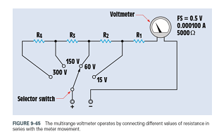
The meter movement described in Question 1 is to be used to construct a multirange voltmeter. The meter is to have voltage ranges of 15 V. 60 V, 150 V, and 300 V (Figure 9-65). Find the values of
Expert Solution & Answer
Want to see the full answer?
Check out a sample textbook solution
Students have asked these similar questions
Draw a easy parallel circuit, using Voltage Source E with 3 resistors. Each resistor has its own voltage drop.
a. Write down an equation describing the total resistance (Rt)
b.Write the equation describing the source current (Is)
c. Write down Kirchoffs Voltage Law for the circuit
1. Draw the circuit diagram in series and parallel connection
Given:
R1= 5Ω
R2= 7Ω
R3= 8Ω
Vt= 9v
How do you convert the circuit of the first one to the second one? This process is for getting ZL=Zth* for maximum power transfer. I need more explanations!
Chapter 9 Solutions
Delmar's Standard Textbook Of Electricity
Ch. 9 - To what is the turning force of a dArsonval meter...Ch. 9 - Prob. 2RQCh. 9 - A DC voltmeter has a resistance of 20,000 per...Ch. 9 - 4. What is the purpose of an ammeter shunt?
Ch. 9 - 5. Name two methods used to make a DC multirange...Ch. 9 - 6. How is an ammeter connected into a circuit?
Ch. 9 - 7. How is a voltmeter connected into a circuit?
Ch. 9 - 8. An ammeter shunt has a voltage drop of 50 mV...Ch. 9 - 9. What type of meter contains its own separate...Ch. 9 - 10. What electrical quantity does the oscilloscope...
Ch. 9 - 11. What is measured on the Y axis of an...Ch. 9 - 12. What is measured on the X axis of an...Ch. 9 - 13. A waveform shown on the display of an...Ch. 9 - 14. What is the major difference between a...Ch. 9 - 15. What two factors determine the turning force...Ch. 9 - You are an electrician on the job. You have been...Ch. 9 - 1. A d'Arsonval meter movement has a full-scale...Ch. 9 - 2. The meter movement described in Question 1 is...Ch. 9 - 3. A meter movement has a full-scale value of . A...Ch. 9 - 4. The meter movement in Question 3 is to be used...Ch. 9 - 5. A digital voltmeter indicates a voltage of 2.5...
Knowledge Booster


Learn more about
Need a deep-dive on the concept behind this application? Look no further. Learn more about this topic, electrical-engineering and related others by exploring similar questions and additional content below.Similar questions
- Referto Figure 8-2. Replace the values shown with the following. Solvefor all theunknownvalues. IT=0.6AR1=470R2=360R3=510R4=430arrow_forwardShown in the figure is an RL series circuit in which R= 10 ohms and L= 0.1 Henry. This is energized by a 24 volt DC source. If the switch is closed at t=o. Find the time when Power across R = Power across L.arrow_forwardPlease solve the following problem 9.33 part b showing all steps to solve. The correct answer to the problem is: (b) 826.2 W, 779.9 W. This problem isn't for a graded assignment, it is just for practice. Thank you so much!!arrow_forward
- Directions: Solve for the given problem. Show your complete solutions. Roundoff your answers into the proper number of significant figures.Find the total resistance, total current and individual currents and individualvoltages in Figure 11 and Figure 12.arrow_forwardI am unsure about how to proceed in this problem, or if I even set it up correctly. Am I supposed to apply KCL to each Node, or set up a Supernode? I have 4 variables, but only came up with 3 equations.arrow_forwardFour resistors, R1 = 100Ω, R2 = 250Ω, R3 = 350Ω and R4 = 200Ω are connected such that the parallel combination of R1 and R2 is connected in series with the parallel combination of R3 and R4. The series-parallel combination is then connected across a 24V DC power supply. Calculate the voltage across R4.arrow_forward
- FIND Current through R1 Current through R2 please answer the following question with clear explanation, show all the workarrow_forwardWhat is the load current for the circuit shown in the figure? Please choose one: a. 9.0 mA b. 7.5 mA c. 3.0 mA D. 6.0 mAarrow_forwardDirections: Solve for the given problem. Show your complete solutions. Roundoff your answers into the proper number of significant figures.Find the total resistance, total current and individual currents and individualvoltages in Figure 12.arrow_forward
- How can I find the voltage v1 through just source transformationsarrow_forwardThe switch was on position a for a long time. At t=0 it is turned to position b. What is the value of the voltage v0(t) at t = 5ms? (Show all the work and explain step by step please, thanks.) Answer is: 10.59Varrow_forwardNumber 27 look at the answer I need to show all work step by steparrow_forward
arrow_back_ios
SEE MORE QUESTIONS
arrow_forward_ios
Recommended textbooks for you
 Delmar's Standard Textbook Of ElectricityElectrical EngineeringISBN:9781337900348Author:Stephen L. HermanPublisher:Cengage Learning
Delmar's Standard Textbook Of Electricity
Electrical Engineering
ISBN:9781337900348
Author:Stephen L. Herman
Publisher:Cengage Learning
Electrical Measuring Instruments - Testing Equipment Electrical - Types of Electrical Meters; Author: Learning Engineering;https://www.youtube.com/watch?v=gkeJzRrwe5k;License: Standard YouTube License, CC-BY
01 - Instantaneous Power in AC Circuit Analysis (Electrical Engineering); Author: Math and Science;https://www.youtube.com/watch?v=If25y4Nhvw4;License: Standard YouTube License, CC-BY