Videos
Using Fig. 9.43, design a problem to help other students better understand impedance.
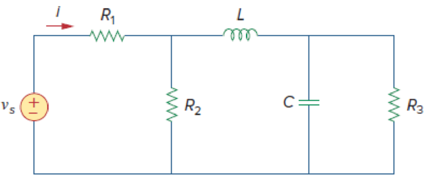
Figure 9.43
Design a problem to make better understand about the impedance using Figure 9.43.
Explanation of Solution
Problem design:
Determine the value of current
Formula used:
Write the expression to convert the time domain expression into phasor domain.
Here,
A is the magnitude,
t is the time, and
Write the expression to calculate the phasor current.
Here,
Write the expression to calculate the impedance of the passive elements resistor, inductor and capacitor.
Here,
Calculation:
The Figure 9.43 is redrawn as Figure 1 by assuming the values for the passive elements.
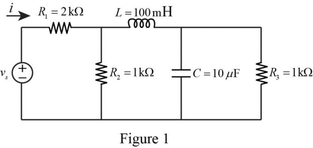
Given voltage equation is,
Here, angular frequency
Use the equation (1) to express the above equation in phasor form.
Substitute
Substitute
Substitute
Substitute
Substitute
The Figure 1 is redrawn as impedance circuit in the following Figure 2.
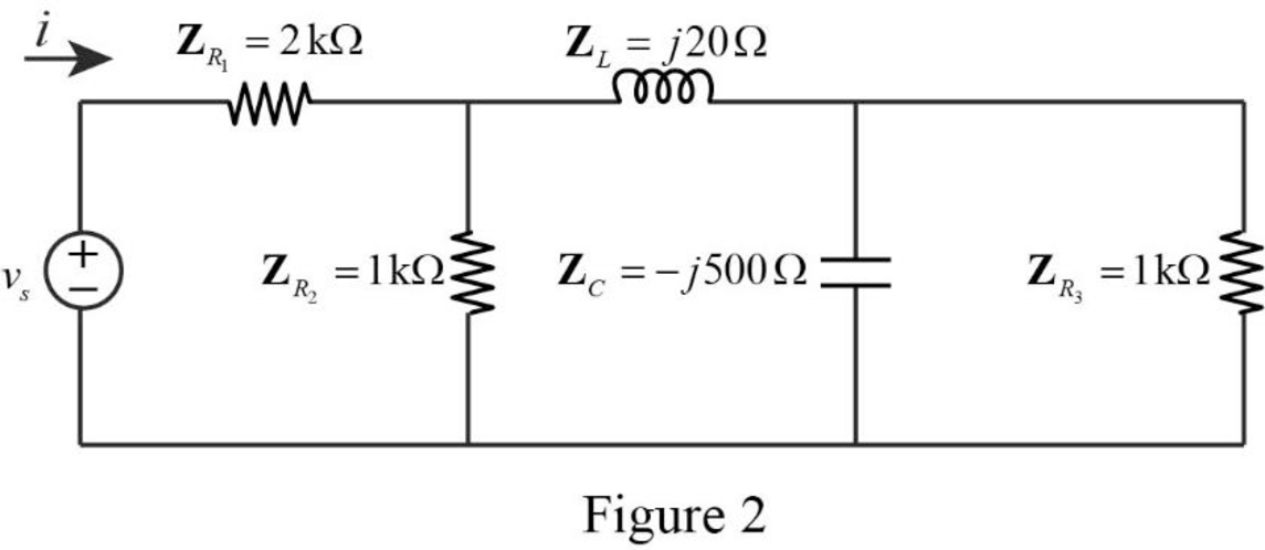
Refer to Figure 2, the impedances
Write the expression to calculate the equivalent capacitance 1 for the parallel connected impedances
Here,
Substitute
The reduced circuit of the Figure 2 is drawn as Figure 3.
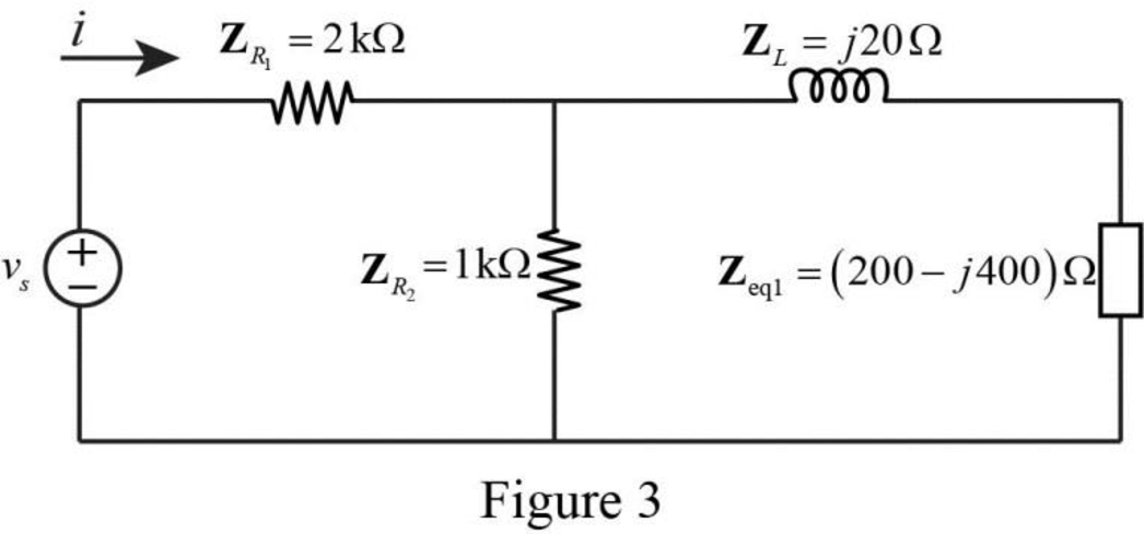
Refer to Figure 3, the impedances
Write the expression to calculate the equivalent capacitance 2 for the series connected impedances
Here,
Substitute
The reduced circuit of the Figure 3 is drawn as Figure 4.
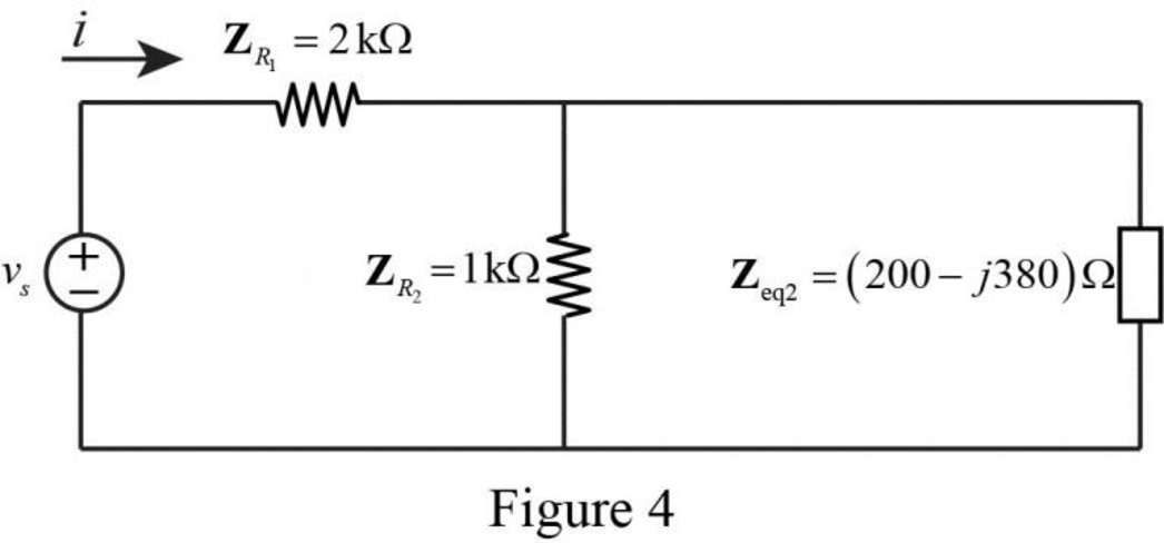
Refer to Figure 4, the impedances
Write the expression to calculate the equivalent capacitance 3 for the parallel connected impedances
Here,
Substitute
The reduced circuit of the Figure 4 is drawn as Figure 5.
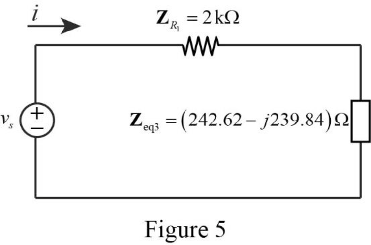
Refer to Figure 5, the impedances
Write the expression to calculate the equivalent capacitance 4 for the series connected impedances
Here,
Substitute
The reduced circuit of the Figure 5 is drawn as Figure 6.
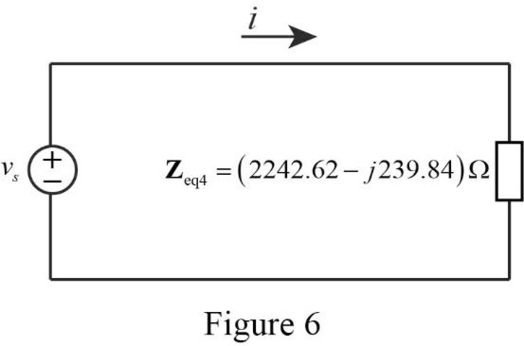
Therefore, the equivalent impedance of the circuit in Figure 1 is,
Substitute
Use the equation (1) to express the above equation in time domain form.
Substitute
Therefore, the value of current
Conclusion:
Thus, the problem to make better understand about the impedance using Figure 9.43 is designed.
Want to see more full solutions like this?
Chapter 9 Solutions
Fundamentals of Electric Circuits
Additional Engineering Textbook Solutions
Basic Engineering Circuit Analysis
Principles and Applications of Electrical Engineering
ELECTRICITY FOR TRADES (LOOSELEAF)
Electric Motors and Control Systems
Engineering Electromagnetics
Introductory Circuit Analysis (13th Edition)


- 1. What impedance vector 0 – j22 represents:A. A pure resistance.B. A pure inductance.C. A pure capacitance.D. An inductance combined with a resistance.arrow_forward9. A capacitor has a resistance of 80ohms when connected to a 50 Hz supply. Calculate the value of capacitance A. 39.79 microfarad B. 39.97 microfarad C. 93.79 microfarad D. 93.97 microfaradarrow_forwardThe admittance for a circuit, G + jB, is 0.02 + j0.20. What is the impedance, R + jX? Provide illustration of the circuit.arrow_forward
- A transmission line has a capacitance of 25 pF / ft. and an inductance of 0.15 µh / ft. Determine the characteristic impedance of the line.arrow_forwardA 6.36 μF capacitor is connected in parallel with a resistance of 500Ω and the combination is connected in series with a 500Ω resistor. The whole circuit is connected across an ac source given by e=300sin(ωt) + 100 sin(3ωt + 30°). If ω = 314 rad/s. find: a)Irms b)Vrms c)total active power d)total power factor e)total reactive power f)total apparent powerarrow_forwardH = 3RM2cos(9ft) where f = frequency, t = time, and the remaining variables are either proportionality constants or material constants. What is the maximum value H could have (algebraic answer)arrow_forward
- Capacitance= 10uF , t≈65 μs, Vfinal=4VPlot capacitor current and voltage graphs. NOTE: if you want you can use falstad online circuit simulator.arrow_forwardThe following values were obtained from a series circuit containing resistance and capacitance: V = 150 V; I = 2.5 A; P = 37.5 W, f = 60 Hz.Calculate (a) Power factor (b) effective resistance (c) capacitive reactance and(d) capacitancearrow_forwardA 160 μF capacitor is connected in series with a 10 Ω resistor. Write the equation of the current when the voltage is 220 Vp? a. 11.4 sin (377t + 59) b. 8.9 sin (377t – 46) c. 9.8 sin (377t + 52) d. 7.2 sin (377t + 46)arrow_forward
- What impedance vector 10 + j22 represents:A. A pure resistance. C. A pure capacitance.B. A pure inductance. D. An inductance combined with a resistance.arrow_forwardThe voltage v(t) across the terminal a and b is a sinusoidal voltage having a frequency w = 100 radians/s. When the inductor current i(t) is in phase with the voltage v(t), the magnitude of the impedance Z (in ohm) seen between the terminals a and b is...arrow_forwardIf the phasor voltage across an element is given by V=100∠120∘ and the phasor current through the same element is given by I=50∠30∘, which of the following basic circuit elements best represents this element? a. Insufficient information is given. b. Capacitor c. Some combination of these basic elements d. Resistor e. Inductorarrow_forward
 Introductory Circuit Analysis (13th Edition)Electrical EngineeringISBN:9780133923605Author:Robert L. BoylestadPublisher:PEARSON
 Delmar's Standard Textbook Of ElectricityElectrical EngineeringISBN:9781337900348Author:Stephen L. HermanPublisher:Cengage Learning
 Programmable Logic ControllersElectrical EngineeringISBN:9780073373843Author:Frank D. PetruzellaPublisher:McGraw-Hill Education
 Fundamentals of Electric CircuitsElectrical EngineeringISBN:9780078028229Author:Charles K Alexander, Matthew SadikuPublisher:McGraw-Hill Education
 Electric Circuits. (11th Edition)Electrical EngineeringISBN:9780134746968Author:James W. Nilsson, Susan RiedelPublisher:PEARSON
 Engineering ElectromagneticsElectrical EngineeringISBN:9780078028151Author:Hayt, William H. (william Hart), Jr, BUCK, John A.Publisher:Mcgraw-hill Education,