EBK MINDTAP FOR HERMAN'S DELMAR'S STAND
7th Edition
ISBN: 9781337900614
Author: Herman
Publisher: VST
expand_more
expand_more
format_list_bulleted
Concept explainers
Videos
Textbook Question
Chapter 9, Problem 4PP
The meter movement in Question 3 is to be used as a multirange ammeter. An Ayrton shunt is to be used to provide full-scale current ranges of 5 A, 1 A, and 0.5 A (Figure 9-66). Find the values of
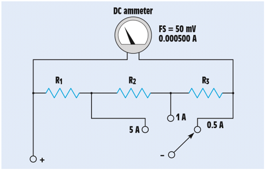
FIGURE 9-66 Ayrton shunt.
Expert Solution & Answer
Want to see the full answer?
Check out a sample textbook solution
Students have asked these similar questions
Please answer all subpart either dislike is ready please sir
All subpart in short please
Determine the sequence of the counter in Figure 9-73.
CLK
000
THE SWITCH HAS BetN
W PositIOn 1 FoR
A LONG TiME
THE INITAL VOLTnsE
ACposs THE Lf
CAPACITUR IS ZERO,
25V
Fwo THE CURRENT i,
AFTER THE SwitCH
Is OPERATZA br E-0
0.5af T
Chapter 9 Solutions
EBK MINDTAP FOR HERMAN'S DELMAR'S STAND
Ch. 9 - To what is the turning force of a dArsonval meter...Ch. 9 - Prob. 2RQCh. 9 - A DC voltmeter has a resistance of 20,000 per...Ch. 9 - 4. What is the purpose of an ammeter shunt?
Ch. 9 - 5. Name two methods used to make a DC multirange...Ch. 9 - 6. How is an ammeter connected into a circuit?
Ch. 9 - 7. How is a voltmeter connected into a circuit?
Ch. 9 - 8. An ammeter shunt has a voltage drop of 50 mV...Ch. 9 - 9. What type of meter contains its own separate...Ch. 9 - 10. What electrical quantity does the oscilloscope...
Ch. 9 - 11. What is measured on the Y axis of an...Ch. 9 - 12. What is measured on the X axis of an...Ch. 9 - 13. A waveform shown on the display of an...Ch. 9 - 14. What is the major difference between a...Ch. 9 - 15. What two factors determine the turning force...Ch. 9 - You are an electrician on the job. You have been...Ch. 9 - 1. A d'Arsonval meter movement has a full-scale...Ch. 9 - 2. The meter movement described in Question 1 is...Ch. 9 - 3. A meter movement has a full-scale value of . A...Ch. 9 - 4. The meter movement in Question 3 is to be used...Ch. 9 - 5. A digital voltmeter indicates a voltage of 2.5...
Knowledge Booster


Learn more about
Need a deep-dive on the concept behind this application? Look no further. Learn more about this topic, electrical-engineering and related others by exploring similar questions and additional content below.Similar questions
- 5. The hypotenuse has a length of 65 in., and side A has a length of 31 in. What is angle X?arrow_forwardAn R-L series circuit contains two resistors and two inductors. The resistors are 86 k and 68 k . The inductors have inductive reactances of 24 k and 56 k . The total voltage is 480 volts. Find the voltage drop across the 56-k inductor.arrow_forward23. Design a binary counter with the sequence shown in the state diagram of Figure 9–75. Up (1 Down FIGURE 9-75arrow_forward
- Q6/ What is the dc source voltage? 0.013 R1 kOhm R232 kohm R3 kohm O 78 V 39 V O 13 Varrow_forwardQUICKLY PLEASE For figure below, determine the voltage across the resistor.arrow_forward4. For the ripple counter in Figure 9-66, show the complete timing diagram for sixteen clock pulses. Show the clock, Qo. Qi, and Q2 waveforms. LLL Do DI D2 CLK C C FIGURE 9-66arrow_forward
- plot the voltage waveforms (vS and vL)=?arrow_forwardIn the circuit given in the figure, what is the variation of Vo voltage according to time?arrow_forwardGiven the following Resistances and Capacitors in Series and Voltage Source: R1 - 7 ohms R2 = 4 ohms C1 = 0.157 Farad C2 = 0.01 Farad Vs = 10,382 Volts Frequency = 86 Hz What is the Amplitude of the voltage across C1?arrow_forward
- Three capacitors 10 µF, 20 µF, 30 μF are connected in series across 150V (sinusoidal). Then identify the correct statement Maximum voltage will be applied across 10 µF Maximum voltage will be applied across 30 µF Maximum voltage will be applied across 20 µF Minimum voltage will be applied across 10 µFarrow_forwardQUESTION 3 A006 nF parallel plate capacitor with air between them has a separation between plates of 0.5 mm Determine t nel placer ino need to keyin unit of each plate in m²-885401ep fourarrow_forwardThe shown circuit is connected for a very long time with all capacitors were initially uncharged. The final charge on Cy and Cy re Q andQ2, respectively You m tar CC E Ez and Ez- 17 E. Find the ratio Q2 Q1 R A Moving to another question wl save tha response hparrow_forward
arrow_back_ios
SEE MORE QUESTIONS
arrow_forward_ios
Recommended textbooks for you
 Delmar's Standard Textbook Of ElectricityElectrical EngineeringISBN:9781337900348Author:Stephen L. HermanPublisher:Cengage Learning
 Electricity for Refrigeration, Heating, and Air C...Mechanical EngineeringISBN:9781337399128Author:Russell E. SmithPublisher:Cengage Learning
Delmar's Standard Textbook Of Electricity
Electrical Engineering
ISBN:9781337900348
Author:Stephen L. Herman
Publisher:Cengage Learning
Electricity for Refrigeration, Heating, and Air C...
Mechanical Engineering
ISBN:9781337399128
Author:Russell E. Smith
Publisher:Cengage Learning
Electrical Measuring Instruments - Testing Equipment Electrical - Types of Electrical Meters; Author: Learning Engineering;https://www.youtube.com/watch?v=gkeJzRrwe5k;License: Standard YouTube License, CC-BY
01 - Instantaneous Power in AC Circuit Analysis (Electrical Engineering); Author: Math and Science;https://www.youtube.com/watch?v=If25y4Nhvw4;License: Standard YouTube License, CC-BY