
Connect 2 Semester Access Card for Fundamentals of Electric Circuits
6th Edition
ISBN: 9781259893674
Author: Charles Alexander, Matthew Sadiku
Publisher: McGraw-Hill Education
expand_more
expand_more
format_list_bulleted
Videos
Textbook Question
Chapter 9, Problem 52P
If  V in the circuit of Fig. 9.59, find Is.
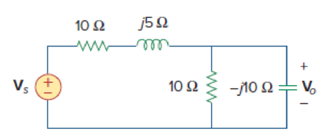
Figure 9.59
Expert Solution & Answer
Want to see the full answer?
Check out a sample textbook solution
Students have asked these similar questions
The admittance (Y) of a circuit is the sum of the phasor current to the phasor voltage.
True
False
QUICKLY
Find the impedance theoretically of a wire if it carries the frequency 10 kHz have a voltage is 8v, the current is 2mA, resistance is 12 kΩ , inductance 27 mH and capacitance 0.2 µf
given circuit, Vk = 12 V, R = 240 Ω, C = 1 μF, L = 40 mH. Theswitch, is closed for a long time for t < 0– . Determine vL(t) for t > 0.
Chapter 9 Solutions
Connect 2 Semester Access Card for Fundamentals of Electric Circuits
Ch. 9.2 - Practice Problem 9.1 Given the sinusoid 45 cos(5t...Ch. 9.2 - Practice Problem 9.2 Find the phase angle between...Ch. 9.3 - Prob. 3PPCh. 9.3 - Express these sinusoids as phasors: (a)...Ch. 9.3 - Find the sinusoids corresponding to these phasors:...Ch. 9.3 - If v1=10sint30V and v2=20cost+45V, find v=v1+v2.Ch. 9.3 - Prob. 7PPCh. 9.4 - If voltage v=25sin100t15V is applied to a 50F...Ch. 9.5 - Refer to Fig. 9.17. Determine v(t) and i(t).Ch. 9.7 - Determine the input impedance of the circuit in...
Ch. 9.7 - Calculate vo in the circuit of Fig. 9.27. Figure...Ch. 9.7 - Find I in the circuit of Fig. 9.30. Figure 9.30Ch. 9.8 - Design an RC circuit to provide a 90 lagging phase...Ch. 9.8 - Refer to the RL circuit in Fig. 9.36. If 10 V is...Ch. 9.8 - In the ac bridge circuit of Fig. 9.37, suppose...Ch. 9 - Which of the following is not a right way to...Ch. 9 - A function that repeats itself after fixed...Ch. 9 - Which of these frequencies has the shorter period?...Ch. 9 - If v1 = 30 sin(t + 10) and v2 = 20 sin(t + 50),...Ch. 9 - The voltage across an inductor leads the current...Ch. 9 - The imaginary part of impedance is called:...Ch. 9 - The impedance of a capacitor increases with...Ch. 9 - At what frequency will the output voltage v0(t) in...Ch. 9 - A series RC circuit has VR = 12 V and VC = 5 V....Ch. 9 - A series RCL circuit has R = 30 , XC = 50 , and XL...Ch. 9 - Given the sinusoidal voltage v(t) = 50 cos (30t +...Ch. 9 - A current source in a linear circuit has...Ch. 9 - Express the following functions in cosine form:...Ch. 9 - Design a problem to help other students better...Ch. 9 - Given v1=45sint+30V and v2=50cost30V, determine...Ch. 9 - For the following pairs of sinusoids, determine...Ch. 9 - If f() = cos + j sin , show that f() = ej.Ch. 9 - Calculate these complex numbers and express your...Ch. 9 - Evaluate the following complex numbers and leave...Ch. 9 - Design a problem to help other students better...Ch. 9 - Find the phasors corresponding to the following...Ch. 9 - Let X=440 and Y=2030. Evaluate the following...Ch. 9 - Evaluate the following complex numbers: (a)...Ch. 9 - Simplify the following expression: (a)...Ch. 9 - Evaluate these determinants: (a) 10+j62j351+j (b)...Ch. 9 - Prob. 16PCh. 9 - Two voltages v1 and v2 appear in series so that...Ch. 9 - Obtain the sinusoids corresponding to each of the...Ch. 9 - Using phasors, find: (a) 3cos20t+105cos20t30 (b)...Ch. 9 - A linear network has a current input 7.5cos10t+30A...Ch. 9 - Simplify the following: (a) ft=5cos2t+154sin2t30...Ch. 9 - An alternating voltage is given by v(t) = 55...Ch. 9 - Apply phasor analysis to evaluate the following:...Ch. 9 - Find v(t) in the following integrodifferential...Ch. 9 - Using phasors, determine i(t) in the following...Ch. 9 - Prob. 26PCh. 9 - A parallel RLC circuit has the node equation...Ch. 9 - Determine the current that flows through an 20-...Ch. 9 - Given that vc(0) = 2 cos(155) V, what is the...Ch. 9 - A voltage v(t) = 100 cos(60t + 20) V is applied to...Ch. 9 - A series RLC circuit has R = 80 , L = 240 mH, and...Ch. 9 - Using Fig. 9.40, design a problem to help other...Ch. 9 - A series RL circuit is connected to a 220-V ac...Ch. 9 - What value of will cause the forced response, vo...Ch. 9 - Find the steady-state current i in the circuit of...Ch. 9 - Using Fig. 9.43, design a problem to help other...Ch. 9 - Determine the admittance Y for the circuit in Fig....Ch. 9 - Using Fig. 9.45, design a problem to help other...Ch. 9 - For the circuit shown in Fig. 9.46, find Zeq and...Ch. 9 - In the circuit of Fig. 9.47, find io when: (a) =...Ch. 9 - Find v(t) in the RLC circuit of Fig. 9.48. Figure...Ch. 9 - Calculate vo(t) in the circuit of Fig. 9.49....Ch. 9 - Find current Io in the circuit shown in Fig. 9.50....Ch. 9 - Calculate i(t) in the circuit of Fig. 9.51. Figure...Ch. 9 - Find current Io in the network of Fig. 9.52....Ch. 9 - If vs = 100 sin(10t + 18) V in the circuit of Fig....Ch. 9 - In the circuit of Fig. 9.54, determine the value...Ch. 9 - Given that vs(t) = 20 sin (100t 40) in Fig. 9.55,...Ch. 9 - Find vs (t) in the circuit of Fig. 9.56 if the...Ch. 9 - Determine vx in the circuit of Fig. 9.57. Let...Ch. 9 - If the voltage vo across the 2- resistor in the...Ch. 9 - If V in the circuit of Fig. 9.59, find Is. Figure...Ch. 9 - Find Io in the circuit of Fig. 9.60.Ch. 9 - In the circuit of Fig. 9.61, Find Vs if Io=300A.Ch. 9 - Find Z in the network of Fig. 9.62, given that...Ch. 9 - At = 377 rad/s, find the input impedance of the...Ch. 9 - At = 1 rad/s, obtain the input admittance in the...Ch. 9 - Using Fig. 9.65, design a problem to help other...Ch. 9 - For the network in Fig. 9.66, find Zin. Let = 100...Ch. 9 - Obtain Zin for the circuit in Fig. 9.67. Figure...Ch. 9 - Find Zeq in the circuit in Fig. 9.68. Figure 9.68Ch. 9 - For the circuit in Fig. 9.69, find the input...Ch. 9 - For the circuit in Fig. 9.70, find the value of...Ch. 9 - Find ZT and Vo in the circuit in Fig. 9.71. Let...Ch. 9 - Determine ZT and I for the circuit in Fig. 9.72....Ch. 9 - For the circuit in Fig. 9.73, calculate ZT and...Ch. 9 - At = 103 rad/s, find the input admittance of each...Ch. 9 - Determine Yeq for the circuit in Fig. 9.75. Figure...Ch. 9 - Find the equivalent admittance Yeq of the circuit...Ch. 9 - Find the equivalent impedance of the circuit in...Ch. 9 - Obtain the equivalent impedance of the circuit in...Ch. 9 - Calculate the value of Zab in the network of Fig....Ch. 9 - Determine the equivalent impedance of the circuit...Ch. 9 - Design an RL circuit to provide a 90 leading phase...Ch. 9 - Design a circuit that will transform a sinusoidal...Ch. 9 - For the following pairs of signals, determine if...Ch. 9 - Refer to the RC circuit in Fig. 9.81. (a)...Ch. 9 - A coil with impedance 8 + j6 is connected in...Ch. 9 - (a) Calculate the phase shift of the circuit in...Ch. 9 - Consider the phase-shifting circuit in Fig. 9.83....Ch. 9 - The ac bridge in Fig. 9.37 is balanced when R1 =...Ch. 9 - A capacitance bridge balances when R1 = 100 , R2 =...Ch. 9 - An inductive bridge balances when R1 = 1.2 k, R2 =...Ch. 9 - The ac bridge shown in Fig. 9.84 is known as a...Ch. 9 - The ac bridge circuit of Fig. 9.85 is called a...Ch. 9 - The circuit shown in Fig. 9.86 is used in a...Ch. 9 - The network in Fig. 9.87 is part of the schematic...Ch. 9 - A series audio circuit is shown in Fig. 9.88. (a)...Ch. 9 - An industrial load is modeled as a series...Ch. 9 - An industrial coil is modeled as a series...Ch. 9 - Figure 9.91 shows a series combination of an...Ch. 9 - A transmission line has a series impedance of and...Ch. 9 - A power transmission system is modeled as shown in...
Knowledge Booster


Learn more about
Need a deep-dive on the concept behind this application? Look no further. Learn more about this topic, electrical-engineering and related others by exploring similar questions and additional content below.Similar questions
- Assume that the voltage drop across the resistor, ER, is 78 V; the voltage drop across the capacitor, EC, is 104 V; and the circuit has a total impedance, Z, of 20 . The frequency of the AC voltage is 60 Hz. Find the missing values. ET ER78V EC104V IT IR IC Z20 R XC VA P VARSC PF Carrow_forwardAssume that the voltage drop across the resistor, ER, is 78 V, that the voltage drop across the inductor, EL, is 104 V, and the circuit has a total impedance, Z, of 20 . The frequency of the AC voltage is 60 Hz. ETITZ20VAPFER78VIRRPEL104VILXLVARsLLarrow_forwardA 250 pico-farad capacitance has a current drawing i = -12.75 cos(250t + 400) A. Determine the equation of voltage in the circuit.arrow_forward
- 9. A capacitor has a resistance of 80ohms when connected to a 50 Hz supply. Calculate the value of capacitance A. 39.79 microfarad B. 39.97 microfarad C. 93.79 microfarad D. 93.97 microfaradarrow_forwarda series r-c circuit takes a current whose equation is i=0.85sin(754t+pi/4) when connected to a source of emf having the equation e=340sin754t. calculate the capacitance of the capacitor, circuit power factor, and power.arrow_forwardA resistor'R' with resistance value of 24 ohm, an inductor 'L' with inductance 20mH, and a capacitor 'C' with capacitance 50 micro Farrad are connected in series with a AC voltage v(t) where v(t) = 50 cos (2 vt + 30 degrees) v. Determine the current i(t) and total impedance if the frequency f is i. 60 Hz ii. 400Hzarrow_forward
- An inductor having an impedance of 6 + j8 is connected across a 200v supply. The real power supplied to it is watts. choices: 4000 3200 2400 1200arrow_forwardA 160 μF capacitor is connected in series with a 10 Ω resistor. Write the equation of the current when the voltage is 220 Vp? a. 11.4 sin (377t + 59) b. 8.9 sin (377t – 46) c. 9.8 sin (377t + 52) d. 7.2 sin (377t + 46)arrow_forwardDetermine the equivalent capacitance, Cab , Lab , and Rab , as seen at terminals a-b.arrow_forward
- A 6.36 μF capacitor is connected in parallel with a resistance of 500Ω and the combination is connected in series with a 500Ω resistor. The whole circuit is connected across an ac source given by e=300sin(ωt) + 100 sin(3ωt + 30°). If ω = 314 rad/s. find: a)Irms b)Vrms c)total active power d)total power factor e)total reactive power f)total apparent powerarrow_forwardUsing the phasors obtain x(n) = cos( (πn)/2) + 1.1 sin((πn)/2).arrow_forwardThe current in an L-R-C series circuit has amplitude 0.120 Aand angular frequency 8.00 * 103 rad/s, and it has its maximum positivevalue at t = 0. The resistance is 95.0 Ω, the inductance is 6.50 mH,and the capacitance is 0.440 mF. For the resistor, inductor, and capacitor,find (a) the voltage amplitudes and (b) the instantaneous voltages att = 0.305 ms.arrow_forward
arrow_back_ios
SEE MORE QUESTIONS
arrow_forward_ios
Recommended textbooks for you
 Delmar's Standard Textbook Of ElectricityElectrical EngineeringISBN:9781337900348Author:Stephen L. HermanPublisher:Cengage Learning
Delmar's Standard Textbook Of Electricity
Electrical Engineering
ISBN:9781337900348
Author:Stephen L. Herman
Publisher:Cengage Learning
Inductors Explained - The basics how inductors work working principle; Author: The Engineering Mindset;https://www.youtube.com/watch?v=KSylo01n5FY;License: Standard Youtube License