
Videos
The ac bridge shown in Fig. 9.84 is known as a Maxwell bridge and is used for accurate measurement of inductance and resistance of a coil in terms of a standard capacitance Cs. Show that when the bridge is balanced,
Lx = R2R3Cs and
Find Lx and Rx for R1 = 40 kΩ, R2 = 1.6 kΩ, R3 = 4 kΩ, and Cs = 0.45 μF.
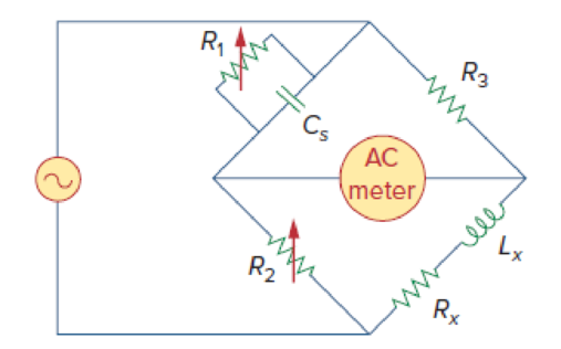
Figure 9.84
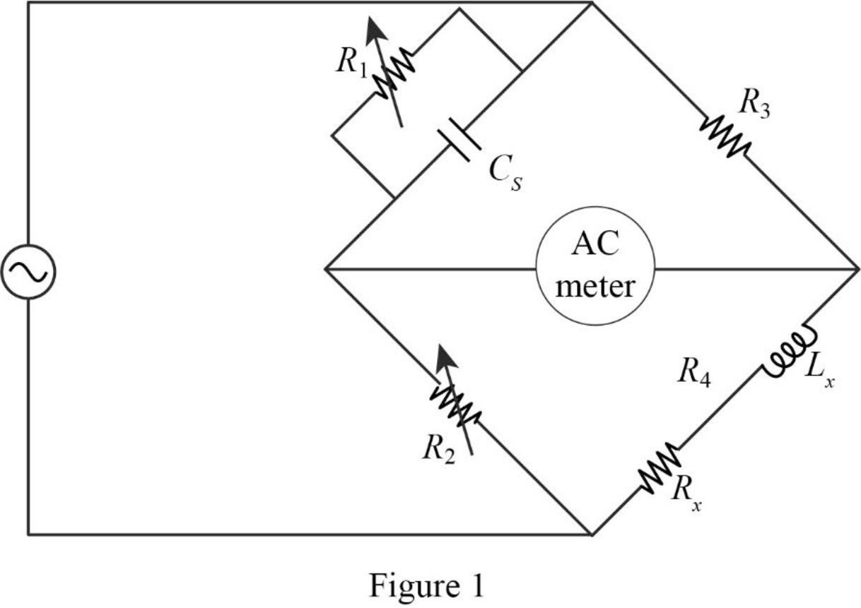
Show that when the bridge in Figure 9.85 is balanced the value of resistor
Answer to Problem 84P
The value of resistor
Explanation of Solution
Given data:
Refer to Figure 9.85 in the textbook.
The value of resistor
The value of resistor
The value of resistor
The value of capacitor
Formula used:
Write a general expression to calculate the impedance of a resistor.
Here,
Write a general expression to calculate the impedance of an inductor.
Here,
Write a general expression to calculate the impedance of a capacitor.
Here,
Calculation:
The given circuit is redrawn as shown in Figure 1.
Use equation (1) to find
Use equation (2) to find
Use equation (3) to find
Now, the impedance diagram of Figure 1 is drawn as shown in Figure 2.
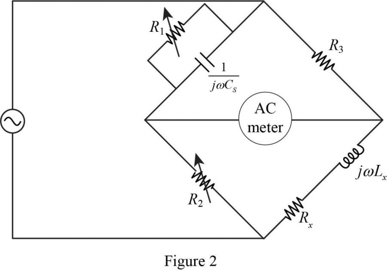
Refer to Figure 2, the impedance of resistor
Therefore, the equivalent impedance
Refer to Figure 2, the impedance of resistor
The equivalent impedance
Let,
The balance of equation of an ac bridge is,
Substitute
Equate the real and imaginary part in above equation.
Simplify the equation (5) to find
Substitute
Substitute
Conclusion:
Thus, when the bridge is balanced, the value of resistor
Want to see more full solutions like this?
Chapter 9 Solutions
EE 98: Fundamentals of Electrical Circuits - With Connect Access


- Show that at a given frequency ω, the circuits will have the same impedance between the terminals a,b ifR1=R21+ω2R22C22,C1=1+ω2R22C22ω2R22C2.2. Find the values of resistance and capacitance that when connectedin series will have the same impedance at 40 krad/s as that of a1000 Ω resistor connected in parallel with a 50 nF capacitor.arrow_forwardThe question concearns RLC circuit, i have 2 sets of data, I need to calculate Z (impedance), R (resistance), Xl (inductive reactance), Xc (capacitive reactance), L (inductance) and C (capacitance) for every measurement in the PDF (first pdf is what do those numbers mean, second pdf is the measurement). I do not know how to calculate it, I do not know the formulas to do that. Please calculate it and show me formula how to calculate it. In this pure inductive load, do i need to calculate all the things i wrote above?arrow_forwardThe question concearns RLC circuit, i have 2 sets of data, I need to calculate Z (impedance), R (resistance), Xl (inductive reactance), Xc (capacitive reactance), L (inductance) and C (capacitance) for every measurement in the PDF (first pdf is what do those numbers mean, second pdf is the measurement). I do not know how to calculate it, I do not know the formulas to do that. Please calculate it and show me formula how to calculate it. In this RL parallel load, do i need to calculate all the things i wrote above?arrow_forward
- A circuit is constructed with an AC generator, a resistor, capacitor and inductor as shown. The generator voltage varies in time as ε =Va - Vb = εmsinωt, where εm = 120 V and ω = 726 radians/second. The values for the remaining circuit components are: R = 62 Ω, L = 95.6 mH, and C = 13.8μF. 4) What is t1, the first time after t = 0 when the voltage across the inductor is zero? 6) What is VC = Vd - Va, the voltage across the capacitor, at time t = 0? Note that VC is a signed number.arrow_forward27. A phasor can be represented or expressed in either rectangular form (x +j y) or polar form (z cis n) True False 28. By convention, values obtain from time domain representation are always real while in phasor domain representation, values are generally expressed in complex form. True False 31. Value of capacitance is usually affected by the following physical dimensions and construction of a capacitor: such as number of turns, its length, its cross-sectional area and the permeability of the core. True Falsearrow_forwardA series L–R–C circuit has a supply input of 5 volts. Given that inductance, L = 5 mH, resistance, R = 75ohm and capacitance, C = 0.2µF, determine (c) the frequency at which the p.d. across the capacitance is a maximum and (d) the value of the maximum voltage across the capacitor. answer: c) 4741 hz, d)10.85voltsarrow_forward
- An AC Wheatstone bridge is supplied by 25V, 50Hz, which is shown in figure C5 is used to find the unknown values of inductance and capacitance. Determine the following, Figure C5 i. Calculate the value of C, if ZD is replaced as capacitor. ii. Calculate the capacitance of the capacitor, if ZD comprise of resistor, inductor and capacitor in series, with R=10 Ω, L = 20mH.arrow_forward. Derive ?? given in Equation 8.9 starting from Equation 8.8.arrow_forwardA voltage of v(t) = 2.9 cos (24 t – 30°) V is applied across a capacitor C = 8.3 mF as shown. What is the magnitude of the current phasor through the capacitor? Please enter your answer in Amps (A), to 3 significant figures below.arrow_forward
- can you solve this quickly? With reference to the source voltage, show the values of v, i, vr, vc in the time plane, the phasor plane and the complex plane.arrow_forwardSolve the circuit by obtaining the state equation. The initial condition voltage value of the capacitance element is VC (0) = 1Volt. R1 = R2 = R3 = R4 = 1Ω, E = 3Volt. State the core solution and the forced solution components in the solution you obtained.arrow_forwardConsider an LRC series circuit with a resistance of 2.5 ohms, capacitance of 0.1 farad, aninductance of 0.1 henry and electromotive force, volts. Given thatAssume there is no initial charge and no initial current on thecapacitor.The equation of the charge q(t), on the capacitor at any time t q(t)=C1e−5t+C2e−20t+0.05cost+0.2sint . (Do not solve the coefficients). a) State the equation of the current, i(t). b) State the transient and the steady-state current. c) What is the current after a long time.arrow_forward
 Introductory Circuit Analysis (13th Edition)Electrical EngineeringISBN:9780133923605Author:Robert L. BoylestadPublisher:PEARSON
 Delmar's Standard Textbook Of ElectricityElectrical EngineeringISBN:9781337900348Author:Stephen L. HermanPublisher:Cengage Learning
 Programmable Logic ControllersElectrical EngineeringISBN:9780073373843Author:Frank D. PetruzellaPublisher:McGraw-Hill Education
 Fundamentals of Electric CircuitsElectrical EngineeringISBN:9780078028229Author:Charles K Alexander, Matthew SadikuPublisher:McGraw-Hill Education
 Electric Circuits. (11th Edition)Electrical EngineeringISBN:9780134746968Author:James W. Nilsson, Susan RiedelPublisher:PEARSON
 Engineering ElectromagneticsElectrical EngineeringISBN:9780078028151Author:Hayt, William H. (william Hart), Jr, BUCK, John A.Publisher:Mcgraw-hill Education,