FUND.OF ELECTRIC CIRCUITS(LL)-W/CONNECT
6th Edition
ISBN: 9781264773305
Author: Alexander
Publisher: MCG CUSTOM
bartleby

Videos

Textbook Question
Book Icon
Chapter 9, Problem 85P

The ac bridge circuit of Fig. 9.85 is called a Wien bridge. It is used for measuring the frequency of a source. Show that when the bridge is balanced,
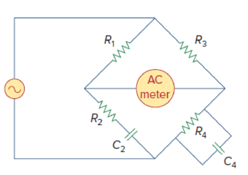
f = 1 2 π R 2 R 4 C 2 C 4

Chapter 9, Problem 85P, The ac bridge circuit of Fig. 9.85 is called a Wien bridge. It is used for measuring the frequency

Figure 9.85

Expert Solution & Answer
Check Mark
To determine

Show that when the bridge in Figure 9.85 is balanced the value of frequency is f=12πR2R4C2C4.

Explanation of Solution

Given data:

Refer to Figure 9.85 in the textbook.

Formula used:

Write a general expression to calculate the impedance of a resistor.

ZR=R        (1)

Here,

R is the value of resistance.

Write a general expression to calculate the impedance of a capacitor.

ZC=1jωC        (2)

Here,

C is the value of capacitance.

Write a general expression to calculate the angular frequency.

ω=2πf        (3)

Here,

f is the value of frequency.

Calculation:

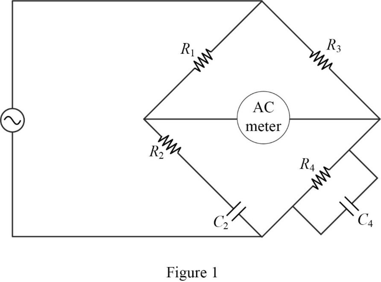
The given circuit is redrawn as shown in Figure 1.

FUND.OF ELECTRIC CIRCUITS(LL)-W/CONNECT, Chapter 9, Problem 85P , additional homework tip  1

Use equation (1) to find ZR1, ZR2, ZR3 and ZR4.

ZR1=R1

ZR2=R2

ZR3=R3

ZR4=R4

Use equation (2) to find ZC2 and ZC4.

ZC2=1jωC2

ZC4=1jωC4

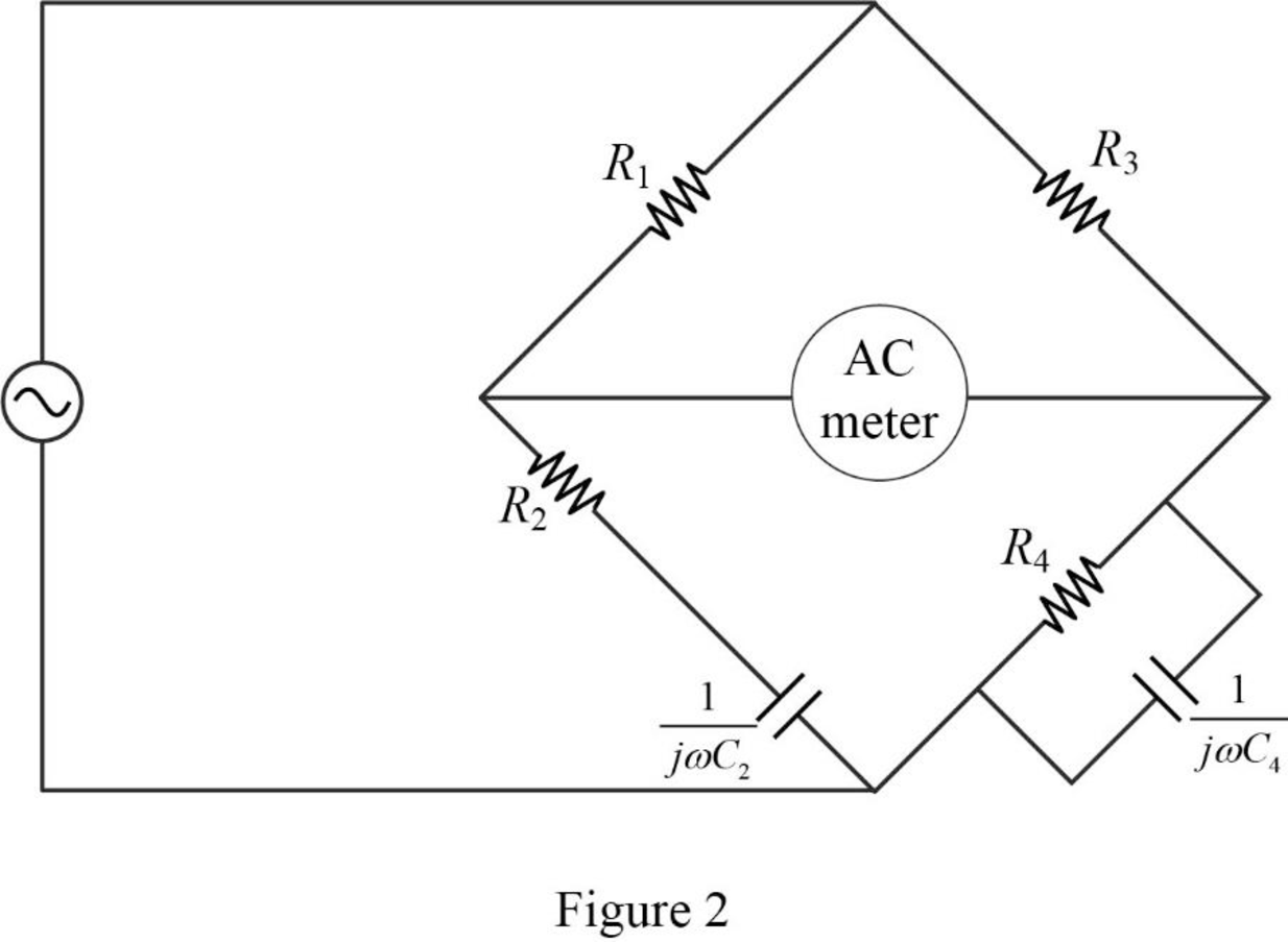
Now, the impedance diagram of Figure 1 is drawn as shown in Figure 2.

FUND.OF ELECTRIC CIRCUITS(LL)-W/CONNECT, Chapter 9, Problem 85P , additional homework tip  2

Refer to Figure 2, the impedance of resistor R2 and the capacitor C2 are connected in series.

Therefore, the equivalent impedance (Z2) is calculated as follows:

Z2=R2+1jωC2=R2jωC2

Refer to Figure 2, the impedance of resistor R4 and the capacitor C4 are connected in parallel.

The equivalent impedance (Z4) is calculated as follows:

Z4=R41jωC4=R4(1jωC4)R4+1jωC4=R4(1jωC4)jωR4C4+1jωC4=R4jωR4C4+1

Simplify the above equation as follows:

Z4=R4j(ωR4C4+1j)=jR4(ωR4C4j)

Let,

Z1=ZR1=R1

Z3=ZR3=R3

The balance of equation of an ac bridge is,

Z4=Z3Z1Z2

The above equation as rearranged as follows:

Z1Z4=Z2Z3

Substitute R1 for Z1, R2jωC2 for Z2, R3 for Z3, and jR4(ωR4C4j) for Z4 in above equation.

jR4R1(ωR4C4j)=R3(R2jωC2)

Take the conjugate of denominator to rationalize the fraction in left hand side.

jR4R1(ωR4C4+j)(ωR4C4j)(ωR4C4+j)=R3R2jR3ωC2(jωR1R42C4j2R4R1)(ωR4C4)2j2=R3R2jR3ωC2(jωR1R42C4(1)R4R1)(ωR4C4)2(1)2=R3R2jR3ωC2{j2=1}(R1R4jωR1R42C4)ω2R42C42+1=R3R2jR3ωC2

R1R4ω2R42C42+1jωR1R42C4ω2R42C42+1=R3R2jR3ωC2

Equate the real and imaginary part in above equation.

R1R4ω2R42C42+1=R3R2        (4)

ωR1R42C4ω2R42C42+1=R3ωC2

ωR1R42C4ω2R42C42+1=R3ωC2        (5)

Divide equation (4) by (5).

(R1R4ω2R42C42+1)(ωR1R42C4ω2R42C42+1)=R3R2(R3ωC2)(R1R4ω2R42C42+1)(ω2R42C42+1ωR1R42C4)=ωR2R3C2jR31ωR4C4=ωR2C2ω2=1R2C2R4C4

Simplify the above equation to find ω.

ω=1R2C2R4C4=1R2C2R4C4

Rearrange equation (3) to find f.

f=ω2π

Substitute 1R2C2R4C4 for ω in above equation to find f.

f=(1R2C2R4C4)2π=12πR2C2R4C4

Conclusion:

Thus, when the bridge is balanced, the value of frequency f=12πR2C2R4C4 is shown.

Want to see more full solutions like this?

Subscribe now to access step-by-step solutions to millions of textbook problems written by subject matter experts!

Chapter 9 Solutions

FUND.OF ELECTRIC CIRCUITS(LL)-W/CONNECT

Ch. 9.7 - Calculate vo in the circuit of Fig. 9.27. Figure...Ch. 9.7 - Find I in the circuit of Fig. 9.30. Figure 9.30Ch. 9.8 - Design an RC circuit to provide a 90 lagging phase...Ch. 9.8 - Refer to the RL circuit in Fig. 9.36. If 10 V is...Ch. 9.8 - In the ac bridge circuit of Fig. 9.37, suppose...Ch. 9 - Which of the following is not a right way to...Ch. 9 - A function that repeats itself after fixed...Ch. 9 - Which of these frequencies has the shorter period?...Ch. 9 - If v1 = 30 sin(t + 10) and v2 = 20 sin(t + 50),...Ch. 9 - The voltage across an inductor leads the current...Ch. 9 - The imaginary part of impedance is called:...Ch. 9 - The impedance of a capacitor increases with...Ch. 9 - At what frequency will the output voltage v0(t) in...Ch. 9 - A series RC circuit has VR = 12 V and VC = 5 V....Ch. 9 - A series RCL circuit has R = 30 , XC = 50 , and XL...Ch. 9 - Given the sinusoidal voltage v(t) = 50 cos (30t +...Ch. 9 - A current source in a linear circuit has...Ch. 9 - Express the following functions in cosine form:...Ch. 9 - Design a problem to help other students better...Ch. 9 - Given v1=45sint+30V and v2=50cost30V, determine...Ch. 9 - For the following pairs of sinusoids, determine...Ch. 9 - If f() = cos + j sin , show that f() = ej.Ch. 9 - Calculate these complex numbers and express your...Ch. 9 - Evaluate the following complex numbers and leave...Ch. 9 - Design a problem to help other students better...Ch. 9 - Find the phasors corresponding to the following...Ch. 9 - Let X=440 and Y=2030. Evaluate the following...Ch. 9 - Evaluate the following complex numbers: (a)...Ch. 9 - Simplify the following expression: (a)...Ch. 9 - Evaluate these determinants: (a) 10+j62j351+j (b)...Ch. 9 - Prob. 16PCh. 9 - Two voltages v1 and v2 appear in series so that...Ch. 9 - Obtain the sinusoids corresponding to each of the...Ch. 9 - Using phasors, find: (a) 3cos20t+105cos20t30 (b)...Ch. 9 - A linear network has a current input 7.5cos10t+30A...Ch. 9 - Simplify the following: (a) ft=5cos2t+154sin2t30...Ch. 9 - An alternating voltage is given by v(t) = 55...Ch. 9 - Apply phasor analysis to evaluate the following:...Ch. 9 - Find v(t) in the following integrodifferential...Ch. 9 - Using phasors, determine i(t) in the following...Ch. 9 - Prob. 26PCh. 9 - A parallel RLC circuit has the node equation...Ch. 9 - Determine the current that flows through an 20-...Ch. 9 - Given that vc(0) = 2 cos(155) V, what is the...Ch. 9 - A voltage v(t) = 100 cos(60t + 20) V is applied to...Ch. 9 - A series RLC circuit has R = 80 , L = 240 mH, and...Ch. 9 - Using Fig. 9.40, design a problem to help other...Ch. 9 - A series RL circuit is connected to a 220-V ac...Ch. 9 - What value of will cause the forced response, vo...Ch. 9 - Find the steady-state current i in the circuit of...Ch. 9 - Using Fig. 9.43, design a problem to help other...Ch. 9 - Determine the admittance Y for the circuit in Fig....Ch. 9 - Using Fig. 9.45, design a problem to help other...Ch. 9 - For the circuit shown in Fig. 9.46, find Zeq and...Ch. 9 - In the circuit of Fig. 9.47, find io when: (a) =...Ch. 9 - Find v(t) in the RLC circuit of Fig. 9.48. Figure...Ch. 9 - Calculate vo(t) in the circuit of Fig. 9.49....Ch. 9 - Find current Io in the circuit shown in Fig. 9.50....Ch. 9 - Calculate i(t) in the circuit of Fig. 9.51. Figure...Ch. 9 - Find current Io in the network of Fig. 9.52....Ch. 9 - If vs = 100 sin(10t + 18) V in the circuit of Fig....Ch. 9 - In the circuit of Fig. 9.54, determine the value...Ch. 9 - Given that vs(t) = 20 sin (100t 40) in Fig. 9.55,...Ch. 9 - Find vs (t) in the circuit of Fig. 9.56 if the...Ch. 9 - Determine vx in the circuit of Fig. 9.57. Let...Ch. 9 - If the voltage vo across the 2- resistor in the...Ch. 9 - If V in the circuit of Fig. 9.59, find Is. Figure...Ch. 9 - Find Io in the circuit of Fig. 9.60.Ch. 9 - In the circuit of Fig. 9.61, Find Vs if Io=300A.Ch. 9 - Find Z in the network of Fig. 9.62, given that...Ch. 9 - At = 377 rad/s, find the input impedance of the...Ch. 9 - At = 1 rad/s, obtain the input admittance in the...Ch. 9 - Using Fig. 9.65, design a problem to help other...Ch. 9 - For the network in Fig. 9.66, find Zin. Let = 100...Ch. 9 - Obtain Zin for the circuit in Fig. 9.67. Figure...Ch. 9 - Find Zeq in the circuit in Fig. 9.68. Figure 9.68Ch. 9 - For the circuit in Fig. 9.69, find the input...Ch. 9 - For the circuit in Fig. 9.70, find the value of...Ch. 9 - Find ZT and Vo in the circuit in Fig. 9.71. Let...Ch. 9 - Determine ZT and I for the circuit in Fig. 9.72....Ch. 9 - For the circuit in Fig. 9.73, calculate ZT and...Ch. 9 - At = 103 rad/s, find the input admittance of each...Ch. 9 - Determine Yeq for the circuit in Fig. 9.75. Figure...Ch. 9 - Find the equivalent admittance Yeq of the circuit...Ch. 9 - Find the equivalent impedance of the circuit in...Ch. 9 - Obtain the equivalent impedance of the circuit in...Ch. 9 - Calculate the value of Zab in the network of Fig....Ch. 9 - Determine the equivalent impedance of the circuit...Ch. 9 - Design an RL circuit to provide a 90 leading phase...Ch. 9 - Design a circuit that will transform a sinusoidal...Ch. 9 - For the following pairs of signals, determine if...Ch. 9 - Refer to the RC circuit in Fig. 9.81. (a)...Ch. 9 - A coil with impedance 8 + j6 is connected in...Ch. 9 - (a) Calculate the phase shift of the circuit in...Ch. 9 - Consider the phase-shifting circuit in Fig. 9.83....Ch. 9 - The ac bridge in Fig. 9.37 is balanced when R1 =...Ch. 9 - A capacitance bridge balances when R1 = 100 , R2 =...Ch. 9 - An inductive bridge balances when R1 = 1.2 k, R2 =...Ch. 9 - The ac bridge shown in Fig. 9.84 is known as a...Ch. 9 - The ac bridge circuit of Fig. 9.85 is called a...Ch. 9 - The circuit shown in Fig. 9.86 is used in a...Ch. 9 - The network in Fig. 9.87 is part of the schematic...Ch. 9 - A series audio circuit is shown in Fig. 9.88. (a)...Ch. 9 - An industrial load is modeled as a series...Ch. 9 - An industrial coil is modeled as a series...Ch. 9 - Figure 9.91 shows a series combination of an...Ch. 9 - A transmission line has a series impedance of and...Ch. 9 - A power transmission system is modeled as shown in...
Knowledge Booster
Background pattern image
Electrical Engineering
Learn more about
Need a deep-dive on the concept behind this application? Look no further. Learn more about this topic, electrical-engineering and related others by exploring similar questions and additional content below.
02 - Sinusoidal AC Voltage Sources in Circuits, Part 1; Author: Math and Science;https://www.youtube.com/watch?v=8zMiIHVMfaw;License: Standard Youtube License