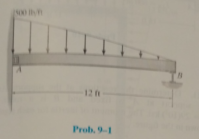
Determine the reactions at the suooorts, then draw the shear and moment diagrams. Assume the support at A is fixed and B is a roller, EI is constant.
The reactions at the supports and to draw the shear and moment diagrams.
Answer to Problem 9.1P
The vertical reaction at support A is
The horizontal reaction at support A is
The reaction moment at support A is
The vertical reaction at support B is
The shear diagram is shown below.

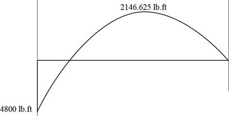
The moment diagram is shown below.
Explanation of Solution
Concept Used:
Write the expression for the net force balance in the vertical direction of the beam.
Here,
Write the expression for the net force balance in the horizontal direction in the beam.
Here,
Write the expression for the net moment about end
Here,
Calculations:
The free body diagram for the beam is shown below.
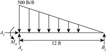
Figure (1)
Here, the vertical reaction at point
Calculate the support reactions using Equation (II).
The uniformly varying load is replaced by a concentrated force of magnitude
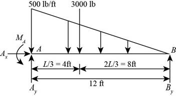
Figure (2)
Consider the moment at point A using Equation (III).
The displacement of the beam for the given load is shown below.
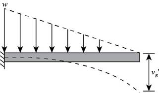
Figure (3)
Calculate the displacement of the beam for the given load.
Here, the displacement of the beam for the given load is
The displacement of the beam for the reaction at point B. is shown below.
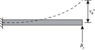
Calculate the displacement of the beam for the given load.
Here, the displacement of the beam for the reaction at point B is
Add Equation (VI) and Equation (VII) for the displacement values according to the compatibility condition.
Substitute
Calculate the vertical reaction at A using Equation (IV).
Substitute
Calculate the bending moment at A using Equation (V).
Substitute
Consider the beam as shown below.
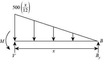
Figure (5)
Write the equation to determine the shear in the beam.
Calculate shear force at a distance
Substitute
Calculate shear force at a distance
Substitute
Calculate shear force at a distance
Substitute
Calculate shear force at a distance
Substitute
Calculate shear force at a distance
Substitute
Substitute
Write the expression for the bending moment.
Calculate moment at a distance
Substitute
Calculate moment at a distance
Substitute
Calculate moment at a distance
Substitute
Calculate moment at a distance
Substitute
Calculate moment at a distance
Substitute
Calculate moment at a distance
Substitute
Conclusion:
The vertical reaction at support A is
The horizontal reaction at support A is
The reaction moment at support A is
The vertical reaction at support B is
The shear diagram is shown below
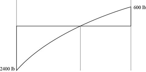
Figure (6)
The moment diagram is shown below

Figure (7)
Want to see more full solutions like this?
Chapter 9 Solutions
Structural Analysis (10th Edition)
Additional Engineering Textbook Solutions
Materials for Civil and Construction Engineers (4th Edition)
Foundation Design: Principles and Practices (3rd Edition)
Elementary Surveying (14th Edition)
Elementary Surveying: An Introduction To Geomatics (15th Edition)
Mechanics of Materials (10th Edition)
Differential Equations: Computing and Modeling (5th Edition), Edwards, Penney & Calvis

- Determine the reactions at the supports, then draw the shear and moment diagrams. EI is constant.arrow_forwardDetermine the moment reactions at the supports, and then draw the shear and moment diagrams. EI is constant.arrow_forwardUsing FORCE METHOD of Statistically Indeterminate Structure, determine the reactions at the supports A, B, and C, then draw the shear and moment diagrams. El is constant.arrow_forward
- Determine the reactions at the supports, then draw the moment diagram. Assume the supports at A and C are fixed and B is roller. EI is constant. (Use moment distribution method method)arrow_forwardDetermine the forces in member BC and BE and the horizontal pin reaction at Garrow_forwardFind the end moment over the supports, reactions at the supports, and draw the shear and bending moment diagram. use three moment equation and assume EI is constant.arrow_forward
- Solve for the reactions and draw the shear and moment diagram. Show complete solution.arrow_forwardUsing Force Method. Determine the reactions at the supports A, B, and C, then draw the shear andmoment diagrams. EI is constant.arrow_forwardDetermine the horizontal and vertical reaction at A, The reaction at G and the force in member AH and JD using method of sections.arrow_forward
- Solve the reactions of the support by Double Integration and Three Moment Equation.arrow_forwardDetermine the support reaction at "A" using the Area Moment Method.arrow_forwardDetermine the reactions at the supports and then draw the shear and moment diagram and deflected shape. Assume A and B are pins and the joints at C and D are fixed connections. EI is constant.arrow_forward

 Structural Analysis (10th Edition)Civil EngineeringISBN:9780134610672Author:Russell C. HibbelerPublisher:PEARSON
 Principles of Foundation Engineering (MindTap Cou...Civil EngineeringISBN:9781337705028Author:Braja M. Das, Nagaratnam SivakuganPublisher:Cengage Learning
 Fundamentals of Structural AnalysisCivil EngineeringISBN:9780073398006Author:Kenneth M. Leet Emeritus, Chia-Ming Uang, Joel LanningPublisher:McGraw-Hill Education
 Traffic and Highway EngineeringCivil EngineeringISBN:9781305156241Author:Garber, Nicholas J.Publisher:Cengage Learning