
Concept explainers
(a)
Use LFRD method to select the
Answer to Problem 9.5.1P
Explanation of Solution
Given:
Thickness of slab, t = 4.5 inches, spacing = 6.5 ft, span length, L = 36 feet, yield stress = 50 Ksi
Construction load = 20 psf, and live load = 175 psf.
The value of
Concept Used:
Calculation:
Using LRFD method, we have
To select the suitable W 16 shape as follows:
Calculate the loads on the beam as follows:
After curing we have,
Where,
between two adjacent beams.
The dead load on the beam after the concrete has cured is:
Where,
Neglecting the beam weight and check for it later.
Calculate the live load on the beam using the following equation:
Where,
Calculate the factored uniformly distributed load after curing has completed by the following formula:
Where,
Substitute the values, we get
Calculate the bending moment on the beam;
Where,
Let’s try a 16-inch deep beam.
Select a shape with the limiting self-weight given by the following formula:
Where, t is the thickness of the concrete slab, d is the depth of the steel beam, a is the distance of the neutral axis from the top,
Estimating weight per unit foot of the steel beam as:
Let’s try for W 16 X 31 and note the properties and dimensions from the Manual.
Calculate the strength of the section as following below:
Where, the compressive force is C, the compressive force of concrete is
Calculate the compressive force in steel as follows:
Where, the area of steel section is
Get the value of
Calculate the compressive force in concrete as following:
Where, b is the width of the concrete slab, t is the thickness of the concrete beam and
The effective flange width is as follows:
Substitute the values in the above equation, we get
Therefore, the compressive force is as follows:
Therefore, the plastic neutral axis lies in the slab.
Calculate the tensile force (T) and compressive force (C) and the position of plastic neutral axis from the top of concrete slab by following formula:
Compute the flexural strength as:
Where,
neutral axis.
Compute the value of Y as following below:
Substitute the values, we get
Calculate the design strength of the section as follows:
Where,
Substitute the values, we get
The flexural strength of the beam after curing is given as:
Where,
Comparing the values of
Thus, the beam is satisfactory in bending after the curing of concrete is complete.
Check for beam weight.
Where,
Substitute the values, we get
Calculate the maximum bending moment on the beam;
Where,
Check the flexural strength of the beam.
Compare the maximum bending moment and the nominal flexural strength
Comparing the values of
Thus, the section is safe in flexure including its self-weight.
Check for the shear:
Checking the value of nominal value of shear strength of
Where,
The maximum shear force is as following for the above conditions:
Substitute the values, we have
Now comparing the two we have
Therefore, the beam is safe in shear and we can use
Calculate the factored uniformly distributed load after curing has completed by following formula:
Load before curing:
Calculate the self-weight of the slab to be allowed by a single beam as
Where,
The dead load on the beam before the concrete has cured
Where, w is the self-weight of the beam
Substitute the values, we have
Now, calculate the live load on the beam as follows
Where the construction load on the slab is
The uniformly distributed factored load can be found as
Where,
Substitute the values in the above equation, we have
Calculate the maximum bending moment on the beam.
Where,
Check the value of the nominal flexural strength of W- sections from the Manual:
Flexural strength of the beam before curing is given as follows:
Where,
Comparing the values of
Thus, the beam is satisfactory before the curing of concrete is complete.
Therefore, W 16 X 31 is satisfactory to use.
Conclusion:
Therefore,
(b)
Use ASD method to select the
Answer to Problem 9.5.1P
Explanation of Solution
Calculation:
Applying Allowable stress design:
Select appropriate W 16 shape
Calculate the loads on the beam as follows:
Before curing
Calculate the self-weight of the slab to be allowed by a single beam as follows:
Where,
between two adjacent beams.
The dead load on the beam after the concrete has cured is:
Where,
Neglecting the beam weight and check for it later.
Calculate the live load on the beam using the following equation:
Where,
Calculate the allowable uniformly distributed load as follows:
Substitute the values as follows
Calculate the bending moment on the beam;
Where,
Let’s try a 16-inch deep beam.
Select a shape with the limiting self-weight given by the following formula:
Where, t is the thickness of the concrete slab, d is the depth of the steel beam, a is the distance of the neutral axis from the top,
Estimating weight per unit foot of the steel beam as:
Let’s try for W 16 X 31 and note the properties and dimensions from the Manual.
Calculate the strength of the section as following below:
Where, the compressive force is C, the compressive force of concrete is
Calculate the compressive force in steel as follows:
Where, the area of steel section is
Get the value of
Calculate the compressive force in concrete as following:
Where, b is the width of the concrete slab, t is the thickness of the concrete beam and
The effective flange width is as follows;
Substitute the values in the above equation, we get
Therefore, the compressive force is as follows:
Therefore, the plastic neutral axis lies in the slab.
Calculate the tensile force (T) and compressive force (C) and the position of plastic neutral axis from the top of concrete slab by following formula:
Compute the flexural strength as:
Where,
neutral axis.
Compute the value of Y as following below:
Substitute the values, we get
Calculate the design strength of the section as follows:
Where,
Substitute the values, we get
Check the nominal value of the flexural strength of W- sections from the manual.
Where,
Comparing the values, we get
Thus, the beam is satisfactory after curing of concrete has completed.
Check for beam weight
Calculating the max bending mo0ment by busing the following formula:
Substitute the values as follows:
Now, checking the flexural strength with the beam taken into consideration:
Compare the maximum bending moment and the nominal flexural strength
Comparing the values of
Thus, the section is safe in flexure including its self-weight.
Check for the shear:
Checking the value of nominal value of shear strength of
Where,
The maximum shear force is as following for the above conditions:
Substitute the values, we have
Now comparing the two we have
Therefore, the beam is safe in shear.
Loading before curing:
Calculate the self-weight of the slab to be allowed by a single beam as follows:
Where,
between two adjacent beams.
The dead load on the beam before the concrete has cured
Where, w is the self-weight of the beam
Substitute the values, we have
Now, calculate the live load on the beam as follows
Where the construction load on the slab is
The uniformly distributed factored load can be found as
Where,
Substitute the values in the above equation, we have
Calculate the maximum bending moment on the beam;
Where,
Check the value of the nominal flexural strength of W- sections from the Manual:
Flexural strength of the beam before curing is given as follows:
Where,
Comparing the values of
Thus, the beam is satisfactory before the curing of concrete is complete.
Conclusion:
Therefore,
(c)
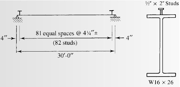
Selecting the stud anchors for the given section.
Answer to Problem 9.5.1P
we will use
Explanation of Solution
Calculation:
We have to check whether the studs satisfy the ASIC specifications.
From AISC specifications the maximum stud diameter will be equal to
Where,
Substitute the values in the equation, we get
Try for,
The area of stud using the following equation as follows:
Where, the diameter of the stud is d.
Substitute
We have the modulus of elasticity of concrete as follows:
Where, the modulus of elasticity of concrete is
unit weight of concrete is
the 28-day compressive strength of concrete is
Substitute
Calculating the shear strength of stud with the following formula:
Substitute the values, we get
Now, the upper limit of the shear strength is as follows:
As, the calculated value is less than the upper limit given by AISC, take the shear strength as:
The number of studs required for the half beam are as follows:
Substitute the values, we have
The number of studs required are as follows:
Substitute the values, we have
Calculate the spacing of the studs as following:
The minimum longitudinal spacing for the studs will be as follows:
Where, the minimum longitudinal spacing for the studs is
Substitute the values, we have
The minimum transversal spacing for the studs will be as follows:
Where, the minimum transversal spacing for the studs is
Substitute the values, we have
The maximum longitudinal spacing for the studs will be as follows:
Where, the maximum longitudinal spacing for the studs is
Substitute the values, we have
Therefore, the upper limit of the spacing is 36 inches.
Calculating the spacing for a stud at each section by the following formula:
Where, S is the spacing required
Conclusion:
Therefore, we will use
Want to see more full solutions like this?
Chapter 9 Solutions
Steel Design (Activate Learning with these NEW titles from Engineering!)


- Use the composite beam tables and select a W-shape and stud anchors for the following conditions: Span length = 18 6 Beam spacing = 9 ft Total slab thickness = 51 2 in. (the slab and deck combination weighs 57 psf). Lightweight concrete with a unit weight of 115 pcf is used Construction load = 20 psf Partition load = 20 psf Live load = 225 psf Fy=50 ksi and fc=4 ksi A cross section of the formed steel deck is shown in Figure P9.8-9. The maximum live-load deflection cannot exceed L/360 (use a lower-bound moment of inertia). a. Use LRFD. b. User ASD.arrow_forwardA concrete floor slab 100 mm thick is cast monolithic with concrete beams 2.0 m on centers. The beams have a span of 4.2 m, web width of 250 mm and overall depth of 450 mm. The tensile reinforcement consists of 4-∅25 mm bars in two rows with 25 mm vertical clear spacing. Use material strengths f’c = 21 MPa and fy = 415 MPa. Tensile steel strain compatible with concrete strain of 0.003 in 3 decimal places.arrow_forwardA W21 x 57 floor beam supports a 5-inch-thick reinforced concrete slab with an effective width b of 75 inches. Sufficient steel anchors are provided to make the beam fully composite. The 28-day compressive strength of the concrete is f,c = 4 ksi. a. Compute the moment of inertia of the transformed section. b. For a positive service load moment of 300 ft-kips, compute the stress at the top of the steel (indicate whether tension or compression), the stress at the bottom of the steel, and the stress at the top of the concrete.arrow_forward
- A composite compression member consists of a W12 x 136 encased in a 20-in. x 22-in. concrete column as shown in Figure Four #10 bars are used for longitudinal reinforcement, and #3 ties spaced 13 inches center-to-center provide the lateral reinforcement. Assume a concrete cover of 2.5 inches to the center of the longitudinal reinforcement. The steel yield stress is Fy = 50 ksi, and Grade 60 reinforcing bars are used. The concrete strength is f,c =5 ksi. Compute the available strength for an effective length of 16 feet with respect to both axes.arrow_forwardA simply supported one way reinforced concrete floor slab has a span of 3 m. It carries a service live load of 8.5 kPa and a service dead load of 1.5 kPa, compressive strength of concrete is 20.7 MPa while the yield strength of reinforcement bars is 414.16 MPa. Use 25 clear cover. Unit weight of reinforced concrete is 24 kN/m3. Determine the minimum required thickness of the slab. Select one: a. 175 mm b. 125 mm c. 150 mm d. 100 mmarrow_forward*Subject: Reinforced prestressed concrete - Civil Engineering *Please refer for my attached formula or guidelines solve this problem A one way cantilever slab having a simple span of 2.0 m. The slab is to carry a uniform dead load of 2.5 KPa and uniform live load of 1.5 Kpa. Fc’=27.6 MPA, fy= 276 MPA for for main bars and temperature bars. Concrete weighs is 23.5 kN/m3. Determine the spacing of the main bars.arrow_forward
- 3) A concrete floor slab 100 mm thick is cast monolithic with concrete beams 2.0 m on centers. The beams have a span of 4.2 m, web width of 250 mm and overall depth of 450 mm. The tensile reinforcement consists of 4-∅25 mm bars in two rows with 25 mm vertical clear spacing. Use material strengths f’c = 21 MPa and fy = 415 MPa. Calculate the following considering a T-geometry: Effective flange width of an interior beam in mm = ___________ Depth of uniform stress block at ultimate stage in mm to the nearest whole number = ___________ Tensile steel strain compatible with concrete strain of 0.003 in 3 decimal places = __________arrow_forwardA concrete floor slab 100mm thick is cast monolithic with concrete beams 2.0m on centers. The beams have a span of 4.2m, web width of 250 mm and overall depth of 450 mm. The tensile reinforcement consists of 4-25 mm diameter bars in two rows with 25mm vertical clear spacing. Use material strengths f’c = 21 MPa and fy = 415 MPa. Calculate the following considering a T-geometry: Effective flange width of an interior beam in mm = Depth of uniform stress block at ultimate stage in mm to the nearest whole number = Tensile steel strain compatible with concrete strain of 0.003 in 3 decimal places =arrow_forwardA beam has a width of 350 mm and a total depth of 700 mm. The loading is as shown in the figure. Material strengths are fc’ = 32 MPa, fy = 400 MPa, and a stirrups diameter of 10 mm. Consider the spacing requirements a. Determine the numbers of 25 mm diameter for bottom reinforcement. b. Unity ratio of the designed section Show complete solution. Need ASAP. thank you.arrow_forward
- Q2 For the composite beam shown, find the moment of resistance of the beam when the maximum bending stress in the timber s (14 MPa). For steel (E = 200 GPa) and for wood (E = 10Gpa) 2 A 7 7 r*arrow_forwardA concrete floor slab 100 mm thick is cast monolithic with concrete beams 2.0 m on centers. The beams have a span of 4.0 m, web width of 250 mm and overall depth of 500 mm. The tensile reinforcement consists of 6 - ø20 mm bars in two rows with 25 mm vertical clear spacing. Use material strength f'c = 21 MPa and fy = 415 MPa. Calculate the following considering a T-geometry: Effective flange width of an interior beam in mm = _______ Depth of uniform stress block at ultimate stage in mm to the neares whole number = _______ Tensile steel strain compatible with concrete strain of 0.003 in 3 decimal places = __________arrow_forwardA beam, which is rectangular, has a base of 250 mm, and d = 575 mm. The beam is singly reinforced, where the recorded strain in the steel is 0.005, and the strain in the concrete is 0.003. fc' = 20.7 MPa, fy = 414.6 MPa. Note: As is not Given a) Determine the value of "a".arrow_forward
 Steel Design (Activate Learning with these NEW ti...Civil EngineeringISBN:9781337094740Author:Segui, William T.Publisher:Cengage Learning