
CODE/MINES MECHANICS MATERIALS >IC<
16th Edition
ISBN: 9781323168950
Author: HIBBELER
Publisher: PEARSON C
expand_more
expand_more
format_list_bulleted
Concept explainers
Videos
Textbook Question
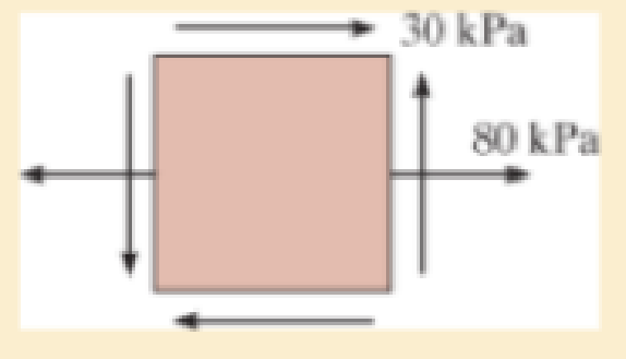
Chapter 9.4, Problem 9.8FP
Also, find the corresponding orientation of the element with respect to the element shown.
Expert Solution & Answer
Want to see the full answer?
Check out a sample textbook solution
Chapter 9 Solutions
CODE/MINES MECHANICS MATERIALS >IC<
Ch. 9.3 - In each case, the state of stress x, y, xy...Ch. 9.3 - Given the state of stress shown on the element,...Ch. 9.3 - Determine the normal stress and shear stress...Ch. 9.3 - Determine the equivalent state of stress on an...Ch. 9.3 - Also, find the corresponding orientation of the...Ch. 9.3 - Determine the equivalent state of stress on an...Ch. 9.3 - Determine the maximum principal stress at point B.Ch. 9.3 - Determine the principal stress at point C.Ch. 9.3 - Prove that the sum of the normal stresses x + y =...Ch. 9.3 - 9-2. The state of stress at a point in a member is...
Ch. 9.3 - Determine the stress components acting on the...Ch. 9.3 - Determine the normal stress and shear stress...Ch. 9.3 - Determine the normal stress and shear stress...Ch. 9.3 - 9-6. Determine the normal stress and shear stress...Ch. 9.3 - 9-7. Determine the normal stress and shear stress...Ch. 9.3 - *9-8. Determine the equivalent state of stress on...Ch. 9.3 - 9-9. Determine the equivalent state of stress on...Ch. 9.3 - Determine the equivalent state of stress on an...Ch. 9.3 - Determine the equivalent slate of stress on an...Ch. 9.3 - *9-12. Determine the equivalent state of stress on...Ch. 9.3 - 9-13. Determine the equivalent state of stress on...Ch. 9.3 - 9-14. The state of stress at a point is shown on...Ch. 9.3 - The state of stress at a point is shown on the...Ch. 9.3 - Determine the equivalent state of stress on an...Ch. 9.3 - Determine the equivalent state of stress on an...Ch. 9.3 - A point on a thin plate is subjected to the two...Ch. 9.3 - Determine the equivalent state of stress on an...Ch. 9.3 - *9-20. Planes AB and BC at a point are subjected...Ch. 9.3 - The stress acting on two planes at a point is...Ch. 9.3 - The grains of wood in the board make an angle of...Ch. 9.3 - The wood beam is subjected to a load of 12 kN. If...Ch. 9.3 - *9-24. The wood beam is subjected to a load of 12...Ch. 9.3 - 9-25. The wooden block will fail if the shear...Ch. 9.3 - 9-26. The bracket is subjected to the force of 3...Ch. 9.3 - 9-27. The bracket is subjected to the force of 3...Ch. 9.3 - 9-28. The 25-mm thick rectangular bar is subjected...Ch. 9.3 - 9-29. The 3-in. diameter shaft is supported by a...Ch. 9.3 - 9-30. The state of stress at a point in a member...Ch. 9.3 - 9-31. Determine the principal stress at point A on...Ch. 9.3 - 9-32. Determine the maximum in-plane shear stress...Ch. 9.3 - 9-33. The clamp bears down on the smooth surface...Ch. 9.3 - 9-34. Determine the principal stress and the...Ch. 9.3 - 9-35. The square steel plate has a thickness of 10...Ch. 9.3 - *9-36. The square steel plate has a thickness of...Ch. 9.3 - The shaft has a diameter d and is subjected to the...Ch. 9.3 - Prob. 9.38PCh. 9.3 - Prob. 9.39PCh. 9.3 - The wide-flange beam is subjected to the 50-kN...Ch. 9.3 - Solve Pro b. 9-40 for point B located on the web...Ch. 9.3 - Prob. 9.42PCh. 9.3 - Prob. 9.43PCh. 9.4 - Use Mohrs circle to determine the normal stress...Ch. 9.4 - Also, find the corresponding orientation of the...Ch. 9.4 - Draw Mohrs circle and determine the principal...Ch. 9.4 - Determine the principal stresses at a point on the...Ch. 9.4 - Determine the principal stresses at point A on the...Ch. 9.4 - Point A is just below the flange.Ch. 9.4 - Solve Prob.93 using Mohrs circle. 93. Determine...Ch. 9.4 - 9-45. Solve Prob. 9-6 using Mohr’s circle.
9-6....Ch. 9.4 - 9-46. Solve Prob. 9-14 using Mohr’s circle.
9-14....Ch. 9.4 - Solve Prob.911 using Mohrs circle. 911. Determine...Ch. 9.4 - *9-48. Solve Prob. 9-12 using Mohr’s...Ch. 9.4 - Solve Prob.916 using Mohrs circle. 916. Determine...Ch. 9.4 - Mohrs circle for the state of stress is shown in...Ch. 9.4 - Prob. 9.51PCh. 9.4 - Prob. 9.52PCh. 9.4 - 9-53. Determine the equivalent state of stress if...Ch. 9.4 - Prob. 9.54PCh. 9.4 - Prob. 9.55PCh. 9.4 - Prob. 9.56PCh. 9.4 - Determine (a) the principal stresses and (b) the...Ch. 9.4 - 9-58. Determine the equivalent state of stress if...Ch. 9.4 - Prob. 9.59PCh. 9.4 - Prob. 9.60PCh. 9.4 - 9-61. Draw Mohr’s circle that describes each of...Ch. 9.4 - The grains of wood in the board make an angle of...Ch. 9.4 - The post is fixed supported at its base and a...Ch. 9.4 - Determine the principal stresses, the maximum...Ch. 9.4 - The thin-walled pipe has an inner diameter of 0.5...Ch. 9.4 - 9-66. Determine the principal stress and maximum...Ch. 9.4 - Prob. 9.67PCh. 9.4 - The rotor shaft of the helicopter is subjected to...Ch. 9.4 - The pedal crank for a bicycle has the cross...Ch. 9.4 - A spherical pressure vessel has an inner radius of...Ch. 9.4 - The cylindrical pressure vessel has an inner...Ch. 9.4 - Determine the normal and shear stresses at point D...Ch. 9.4 - Determine the principal stress at point D, Which...Ch. 9.4 - If the box wrench is subjected to the 50 lb force,...Ch. 9.4 - If the box wrench is subjected to the 50-lb force,...Ch. 9.4 - Prob. 9.76PCh. 9.5 - Draw the three Mohrs circles that describe each of...Ch. 9.5 - Draw the three Mohrs circles that describe the...Ch. 9.5 - 9-79. The stress at a point is shown on the...Ch. 9.5 - Determine the principal stresses and the absolute...Ch. 9.5 - 9-81. The stress at a point is shown on the...Ch. 9.5 - Determine the principal stresses and the absolute...Ch. 9.5 - Determine the principal stresses and the absolute...Ch. 9.5 - Prob. 9.85PCh. 9.5 - Prob. 9.86PCh. 9.5 - 9-87. Determine the principal stresses and...Ch. 9.5 - *9.88. Determine the principal stresses and...Ch. 9 - Prob. 9.89RPCh. 9 - Prob. 9.90RPCh. 9 - Prob. 9.91RPCh. 9 - The steel pipe has an inner diameter of 2.75 in....Ch. 9 - Determine the equivalent state of stress If an...Ch. 9 - The crane is used to support the 350-lb load....Ch. 9 - Determine the equivalent state of stress on an...Ch. 9 - The propeller shaft of the tugboat is subjected to...Ch. 9 - Determine the principal stresses in the box beam...Ch. 9 - Determine (a) the principal stresses and (b) the...Ch. 9 - Determine the stress components acting on the...
Additional Engineering Textbook Solutions
Find more solutions based on key concepts
What is the importance of modeling in engineering? How are the mathematical models for engineering processes pr...
HEAT+MASS TRANSFER:FUND.+APPL.
19.8 Calculate the allowable tensile load for the connection shown. The plates are ASTM A36 steel and the weld ...
Applied Statics and Strength of Materials (6th Edition)
Define or describe each type of fluid: (a) viscoelastic fluid (b) pseudoplastic fluid (c) dilatant fluid (d) Bi...
Fluid Mechanics: Fundamentals and Applications
Locate the centroid of the area. Prob. 9-17
Engineering Mechanics: Statics
A nozzle at A discharges water with an initial velocity of 36 ft/s at an angle with the horizontal. Determine ...
Vector Mechanics for Engineers: Dynamics
List several uses of the arbor press.
Machine Tool Practices (10th Edition)
Knowledge Booster


Learn more about
Need a deep-dive on the concept behind this application? Look no further. Learn more about this topic, mechanical-engineering and related others by exploring similar questions and additional content below.Similar questions
- Determine Ix for the triangular region shown.arrow_forwardA circular region of radius R/2 is cut out from the circular region of radius R as shown. For what distance d will kx for the new region be the same as kx (for the region before the cutout was removed?arrow_forwardFor the shaded region shown, determine (a) Ix and Iy; and (b) Ix and Iy using the parallel axis theorem and the results of part (a).arrow_forward
- It can be show that a plane area may he represented by a vector A=A, where A is the area and represents a unit vector normal to the piano: of the area. Show that the area vector of the parallelogram formed by the vectors a and b shown in the figure is A=ab.arrow_forwardGiven that P=120lb and Q=130lb, find the rectangular representation of P+Q.arrow_forwardUse integration to find Ix,Iy, and Ixy for the shaded region shown.arrow_forward
- For the position vectors P and Q shown, determine the orthogonal component of P Ă— Q in the direction of OA.arrow_forwardThe equation of the catenary shown is y = 100 cosh (x/100) where x and y are measured in feet (the catenary is the shape of a cable suspended between two points). Locate the y-coordinate 0f the centroid of the catenary by numerical integration using x=25ft.arrow_forwardThe intensity of the line loading acting on a quarter circle is w=w0(2/). Use intergration to determine the resultant of the loading and its line of action.arrow_forward
arrow_back_ios
arrow_forward_ios
Recommended textbooks for you
 International Edition---engineering Mechanics: St...Mechanical EngineeringISBN:9781305501607Author:Andrew Pytel And Jaan KiusalaasPublisher:CENGAGE L
International Edition---engineering Mechanics: St...
Mechanical Engineering
ISBN:9781305501607
Author:Andrew Pytel And Jaan Kiusalaas
Publisher:CENGAGE L
Dislocations and Plastic Deformation; Author: LearnChemE;https://www.youtube.com/watch?v=cpvTwYAUeA8;License: Standard Youtube License