
FUNDAMENTALS OF ELECTRIC...(LL)>CUSTOM<
6th Edition
ISBN: 9781260104639
Author: Alexander
Publisher: MCG CUSTOM
expand_more
expand_more
format_list_bulleted
Concept explainers
Videos
Textbook Question
Chapter 9.8, Problem 14PP
Refer to the RL circuit in Fig. 9.36. If 10 V is applied to the input, find the magnitude and the phase shift produced at 5 kHz. Specify whether the phase shift is leading or lagging.
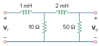
Figure 9.36
Expert Solution & Answer
Want to see the full answer?
Check out a sample textbook solution
Students have asked these similar questions
b) Find the rms current flowing in an AC capacitive circuit when a 4μF capacitor is connected across a 880V, 60Hz supply.
determine the inductive reactance of rlc series ac circuit given the ff:
rms current=7.5A
voltage=5V
resistance=150ohms
capacitive resitance=160ohm
source average power=2.5W
6. What is the sinusoidal expression of current through circuit contain only capacitor?
(Where C=20μF, v=4 sin(1000t+20) V
Chapter 9 Solutions
FUNDAMENTALS OF ELECTRIC...(LL)>CUSTOM<
Ch. 9.2 - Practice Problem 9.1 Given the sinusoid 45 cos(5t...Ch. 9.2 - Practice Problem 9.2 Find the phase angle between...Ch. 9.3 - Prob. 3PPCh. 9.3 - Express these sinusoids as phasors: (a)...Ch. 9.3 - Find the sinusoids corresponding to these phasors:...Ch. 9.3 - If v1=10sint30V and v2=20cost+45V, find v=v1+v2.Ch. 9.3 - Prob. 7PPCh. 9.4 - If voltage v=25sin100t15V is applied to a 50F...Ch. 9.5 - Refer to Fig. 9.17. Determine v(t) and i(t).Ch. 9.7 - Determine the input impedance of the circuit in...
Ch. 9.7 - Calculate vo in the circuit of Fig. 9.27. Figure...Ch. 9.7 - Find I in the circuit of Fig. 9.30. Figure 9.30Ch. 9.8 - Design an RC circuit to provide a 90 lagging phase...Ch. 9.8 - Refer to the RL circuit in Fig. 9.36. If 10 V is...Ch. 9.8 - In the ac bridge circuit of Fig. 9.37, suppose...Ch. 9 - Which of the following is not a right way to...Ch. 9 - A function that repeats itself after fixed...Ch. 9 - Which of these frequencies has the shorter period?...Ch. 9 - If v1 = 30 sin(t + 10) and v2 = 20 sin(t + 50),...Ch. 9 - The voltage across an inductor leads the current...Ch. 9 - The imaginary part of impedance is called:...Ch. 9 - The impedance of a capacitor increases with...Ch. 9 - At what frequency will the output voltage v0(t) in...Ch. 9 - A series RC circuit has VR = 12 V and VC = 5 V....Ch. 9 - A series RCL circuit has R = 30 , XC = 50 , and XL...Ch. 9 - Given the sinusoidal voltage v(t) = 50 cos (30t +...Ch. 9 - A current source in a linear circuit has...Ch. 9 - Express the following functions in cosine form:...Ch. 9 - Design a problem to help other students better...Ch. 9 - Given v1=45sint+30V and v2=50cost30V, determine...Ch. 9 - For the following pairs of sinusoids, determine...Ch. 9 - If f() = cos + j sin , show that f() = ej.Ch. 9 - Calculate these complex numbers and express your...Ch. 9 - Evaluate the following complex numbers and leave...Ch. 9 - Design a problem to help other students better...Ch. 9 - Find the phasors corresponding to the following...Ch. 9 - Let X=440 and Y=2030. Evaluate the following...Ch. 9 - Evaluate the following complex numbers: (a)...Ch. 9 - Simplify the following expression: (a)...Ch. 9 - Evaluate these determinants: (a) 10+j62j351+j (b)...Ch. 9 - Prob. 16PCh. 9 - Two voltages v1 and v2 appear in series so that...Ch. 9 - Obtain the sinusoids corresponding to each of the...Ch. 9 - Using phasors, find: (a) 3cos20t+105cos20t30 (b)...Ch. 9 - A linear network has a current input 7.5cos10t+30A...Ch. 9 - Simplify the following: (a) ft=5cos2t+154sin2t30...Ch. 9 - An alternating voltage is given by v(t) = 55...Ch. 9 - Apply phasor analysis to evaluate the following:...Ch. 9 - Find v(t) in the following integrodifferential...Ch. 9 - Using phasors, determine i(t) in the following...Ch. 9 - Prob. 26PCh. 9 - A parallel RLC circuit has the node equation...Ch. 9 - Determine the current that flows through an 20-...Ch. 9 - Given that vc(0) = 2 cos(155) V, what is the...Ch. 9 - A voltage v(t) = 100 cos(60t + 20) V is applied to...Ch. 9 - A series RLC circuit has R = 80 , L = 240 mH, and...Ch. 9 - Using Fig. 9.40, design a problem to help other...Ch. 9 - A series RL circuit is connected to a 220-V ac...Ch. 9 - What value of will cause the forced response, vo...Ch. 9 - Find the steady-state current i in the circuit of...Ch. 9 - Using Fig. 9.43, design a problem to help other...Ch. 9 - Determine the admittance Y for the circuit in Fig....Ch. 9 - Using Fig. 9.45, design a problem to help other...Ch. 9 - For the circuit shown in Fig. 9.46, find Zeq and...Ch. 9 - In the circuit of Fig. 9.47, find io when: (a) =...Ch. 9 - Find v(t) in the RLC circuit of Fig. 9.48. Figure...Ch. 9 - Calculate vo(t) in the circuit of Fig. 9.49....Ch. 9 - Find current Io in the circuit shown in Fig. 9.50....Ch. 9 - Calculate i(t) in the circuit of Fig. 9.51. Figure...Ch. 9 - Find current Io in the network of Fig. 9.52....Ch. 9 - If vs = 100 sin(10t + 18) V in the circuit of Fig....Ch. 9 - In the circuit of Fig. 9.54, determine the value...Ch. 9 - Given that vs(t) = 20 sin (100t 40) in Fig. 9.55,...Ch. 9 - Find vs (t) in the circuit of Fig. 9.56 if the...Ch. 9 - Determine vx in the circuit of Fig. 9.57. Let...Ch. 9 - If the voltage vo across the 2- resistor in the...Ch. 9 - If V in the circuit of Fig. 9.59, find Is. Figure...Ch. 9 - Find Io in the circuit of Fig. 9.60.Ch. 9 - In the circuit of Fig. 9.61, Find Vs if Io=300A.Ch. 9 - Find Z in the network of Fig. 9.62, given that...Ch. 9 - At = 377 rad/s, find the input impedance of the...Ch. 9 - At = 1 rad/s, obtain the input admittance in the...Ch. 9 - Using Fig. 9.65, design a problem to help other...Ch. 9 - For the network in Fig. 9.66, find Zin. Let = 100...Ch. 9 - Obtain Zin for the circuit in Fig. 9.67. Figure...Ch. 9 - Find Zeq in the circuit in Fig. 9.68. Figure 9.68Ch. 9 - For the circuit in Fig. 9.69, find the input...Ch. 9 - For the circuit in Fig. 9.70, find the value of...Ch. 9 - Find ZT and Vo in the circuit in Fig. 9.71. Let...Ch. 9 - Determine ZT and I for the circuit in Fig. 9.72....Ch. 9 - For the circuit in Fig. 9.73, calculate ZT and...Ch. 9 - At = 103 rad/s, find the input admittance of each...Ch. 9 - Determine Yeq for the circuit in Fig. 9.75. Figure...Ch. 9 - Find the equivalent admittance Yeq of the circuit...Ch. 9 - Find the equivalent impedance of the circuit in...Ch. 9 - Obtain the equivalent impedance of the circuit in...Ch. 9 - Calculate the value of Zab in the network of Fig....Ch. 9 - Determine the equivalent impedance of the circuit...Ch. 9 - Design an RL circuit to provide a 90 leading phase...Ch. 9 - Design a circuit that will transform a sinusoidal...Ch. 9 - For the following pairs of signals, determine if...Ch. 9 - Refer to the RC circuit in Fig. 9.81. (a)...Ch. 9 - A coil with impedance 8 + j6 is connected in...Ch. 9 - (a) Calculate the phase shift of the circuit in...Ch. 9 - Consider the phase-shifting circuit in Fig. 9.83....Ch. 9 - The ac bridge in Fig. 9.37 is balanced when R1 =...Ch. 9 - A capacitance bridge balances when R1 = 100 , R2 =...Ch. 9 - An inductive bridge balances when R1 = 1.2 k, R2 =...Ch. 9 - The ac bridge shown in Fig. 9.84 is known as a...Ch. 9 - The ac bridge circuit of Fig. 9.85 is called a...Ch. 9 - The circuit shown in Fig. 9.86 is used in a...Ch. 9 - The network in Fig. 9.87 is part of the schematic...Ch. 9 - A series audio circuit is shown in Fig. 9.88. (a)...Ch. 9 - An industrial load is modeled as a series...Ch. 9 - An industrial coil is modeled as a series...Ch. 9 - Figure 9.91 shows a series combination of an...Ch. 9 - A transmission line has a series impedance of and...Ch. 9 - A power transmission system is modeled as shown in...
Knowledge Booster


Learn more about
Need a deep-dive on the concept behind this application? Look no further. Learn more about this topic, electrical-engineering and related others by exploring similar questions and additional content below.Similar questions
- Using the phasors obtain x(n) = cos( (πn)/2) + 1.1 sin((πn)/2).arrow_forwardUsing the phase shift theta= 72° from the Experiment, determine the value of the capacitance, C, of the capacitor shown. Vr(t) = 0.93612 cos( 4000 t - 72° ) Varrow_forwardUse CTFT table and properties to find the numerical value of x(t) at t=0.75 if x(t)= 3 sinc (2t) * sinc (4t) : Select one: a. 0.75 sinc (1.5) b. None of the given options c. 3 sinc (1.5) + 3 sinc (3) d. 3 sinc (1.5) sinc (3) e. 3/8 rect (1.5) rect (3)arrow_forward
- What is the product of two complex numbers 4 + 3j and 2+ 2j where j = sqrt (1-) in phasor notation? Write the answer in the form, to make it easy to type, magnitude AT angle in radians.arrow_forwardH = 3RM2cos(9ft) where f = frequency, t = time, and the remaining variables are either proportionality constants or material constants. What is the maximum value H could have (algebraic answer)arrow_forwardA circuit has an ac voltage source and a resistor and capacitorconnected in series. There is no inductor. The ac voltage source hasvoltage amplitude 900 V and angular frequency v = 20.0 rad/s. Thevoltage amplitude across the capacitor is 500 V. The resistor has resistanceR = 300 Ω. What is the average rate at which the ac source supplies electrical energy to the circuit?arrow_forward
- The current in an L-R-C series circuit has amplitude 0.120 Aand angular frequency 8.00 * 103 rad/s, and it has its maximum positivevalue at t = 0. The resistance is 95.0 Ω, the inductance is 6.50 mH,and the capacitance is 0.440 mF. For the resistor, inductor, and capacitor,find (a) the voltage amplitudes and (b) the instantaneous voltages att = 0.305 ms.arrow_forwardFor the circuit shown below, if E =30 sin(377t + 20°) what is the sinusoidal expression for the current?: A)i =7.07 sin(377t + 20°) B)i =10 sin(377t - 20°) C)i =10 sin(377t + 20°)arrow_forwardSolve the question and show solution. Note: Find the value of capacitor and draw the vector diagram of the impedance, power triangle and voltage triangle. Clarification on the value of the inductor is 51.34 mH and the power factor of the circuit is 0.54305. The circuit is capacitive. Lastly, Pt = 1.097 kW. (Sorry for the poor image quality) Thanks!!!arrow_forward
- The voltage v(t) across the terminal a and b is a sinusoidal voltage having a frequency w = 100 radians/s. When the inductor current i(t) is in phase with the voltage v(t), the magnitude of the impedance Z (in ohm) seen between the terminals a and b is...arrow_forwardA series RLC AC circuit has R = 425 Ω, L =1.25 H, C = 3.50 µF, ω=377 s-1, and ΔVmax= 150 V. (a) Determine the inductive reactance, the capacitive reactance, and the impedance of the circuit. Find both the maximum voltage and the instantaneous voltage across each element.arrow_forwardThe phase angle between the input waveform and the capacitor can then be measured using thefollowing equation, sin(ω t) = sin(2π f t) and θ = 2π f t the difference in the phase angle is, ∆(θ) = 2πf∆t, in radians Resistor = 1 kΩ Capacitor = 100nF Peak voltage (AC Voltage) = 2V Frequency = 1KHz Where ∆θ is the phase difference, ∆t is the time difference and can be found as shown in the image below.What is the Value of the phase shift, ∆(θ) =?arrow_forward
arrow_back_ios
SEE MORE QUESTIONS
arrow_forward_ios
Recommended textbooks for you
 Introductory Circuit Analysis (13th Edition)Electrical EngineeringISBN:9780133923605Author:Robert L. BoylestadPublisher:PEARSON
 Delmar's Standard Textbook Of ElectricityElectrical EngineeringISBN:9781337900348Author:Stephen L. HermanPublisher:Cengage Learning
 Programmable Logic ControllersElectrical EngineeringISBN:9780073373843Author:Frank D. PetruzellaPublisher:McGraw-Hill Education
 Fundamentals of Electric CircuitsElectrical EngineeringISBN:9780078028229Author:Charles K Alexander, Matthew SadikuPublisher:McGraw-Hill Education
 Electric Circuits. (11th Edition)Electrical EngineeringISBN:9780134746968Author:James W. Nilsson, Susan RiedelPublisher:PEARSON
 Engineering ElectromagneticsElectrical EngineeringISBN:9780078028151Author:Hayt, William H. (william Hart), Jr, BUCK, John A.Publisher:Mcgraw-hill Education,
Introductory Circuit Analysis (13th Edition)
Electrical Engineering
ISBN:9780133923605
Author:Robert L. Boylestad
Publisher:PEARSON
Delmar's Standard Textbook Of Electricity
Electrical Engineering
ISBN:9781337900348
Author:Stephen L. Herman
Publisher:Cengage Learning
Programmable Logic Controllers
Electrical Engineering
ISBN:9780073373843
Author:Frank D. Petruzella
Publisher:McGraw-Hill Education
Fundamentals of Electric Circuits
Electrical Engineering
ISBN:9780078028229
Author:Charles K Alexander, Matthew Sadiku
Publisher:McGraw-Hill Education
Electric Circuits. (11th Edition)
Electrical Engineering
ISBN:9780134746968
Author:James W. Nilsson, Susan Riedel
Publisher:PEARSON
Engineering Electromagnetics
Electrical Engineering
ISBN:9780078028151
Author:Hayt, William H. (william Hart), Jr, BUCK, John A.
Publisher:Mcgraw-hill Education,
Nodal Analysis for Circuits Explained; Author: Engineer4Free;https://www.youtube.com/watch?v=f-sbANgw4fo;License: Standard Youtube License