
Concept explainers
Videos
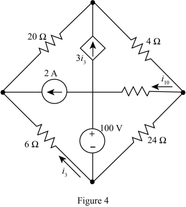
Draw a suitable tree and use general loop analysis to find i10 in the circuit of (a) Fig. A1.13a by writing just one equation with i10 as the variable; (b) Fig. A1.13b by writing just two equations with i10 and i3 as the variables.
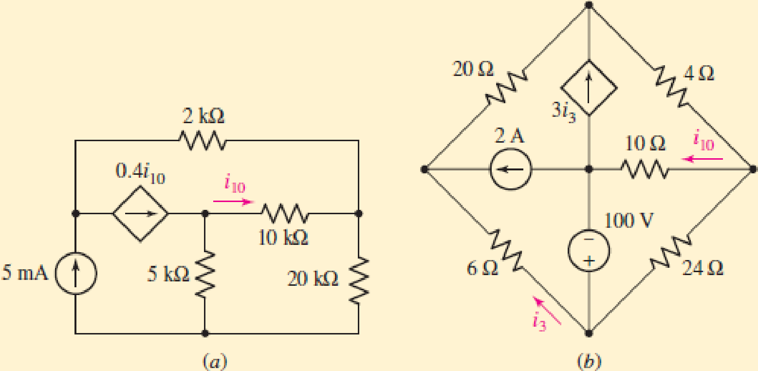
(a)
The value of the current
Answer to Problem 2P
The value of the current
Explanation of Solution
Given data:
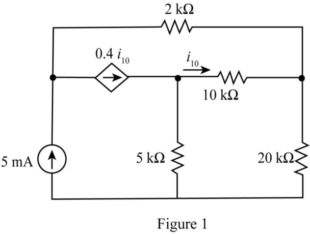
The given diagram is shown in Figure 1.
Calculation:
Draw the tree diagram of the given network.
The required diagram is shown in Figure 2.
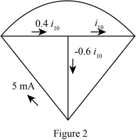
The current
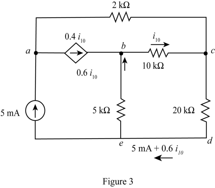
The modified diagram is shown in Figure 3.
The conversion from
The conversion from
The conversion from
The conversion from
The conversion from
The conversion from
Write the KVL for the loop
The conversion from
The conversion from
Hence, the current
Conclusion:
Therefore, the value of the current
(b)
The value of the current
Answer to Problem 2P
The value of the current
Explanation of Solution
Given data:
The given diagram is shown in Figure 4.
Calculation:
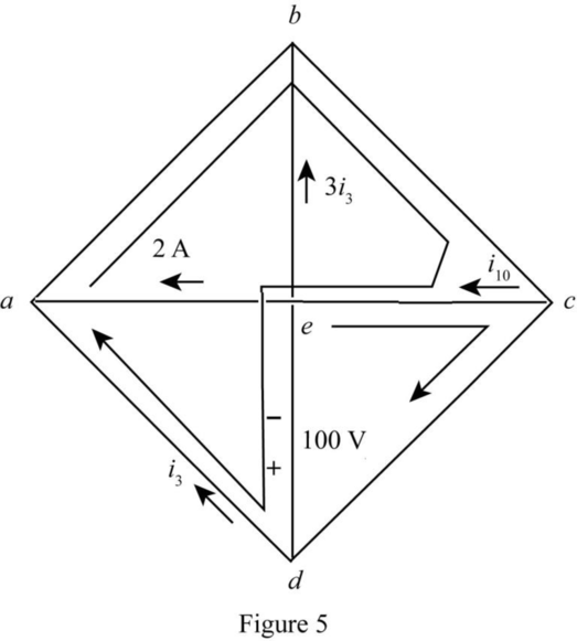
Draw tree diagram for the given network.
The required diagram is shown in Figure 5.
Write the KVL for the loop
Write the KVL for the loop
Substitute
Conclusion:
Therefore, the value of the current
Want to see more full solutions like this?
Chapter A1 Solutions
Engineering Circuit Analysis
Additional Engineering Textbook Solutions
Basic Engineering Circuit Analysis
Principles and Applications of Electrical Engineering
ELECTRICITY FOR TRADES (LOOSELEAF)
Microelectronics: Circuit Analysis and Design
Electronics Fundamentals: Circuits, Devices & Applications
Electric Circuits. (11th Edition)


- B=6, so the feeder reactance is 16 %. Fig. Q2 shows a typical network of a small power station. Calculate the fault level at busbar C using 36 MVA as the base. The feeder reactance is 16 %.arrow_forwardDETERMINING CAPACITY UTILIZATION AND EFFICIENCY Sara James Bakery has a plant for processing Deluxe breakfast rolls and wants to better understandits capability. Last week the facility produced 148,000 rolls. The effective capacity is 175,000 rolls. Theproduction line operates 7 days per week, with three 8-hour shifts per day. The line was designed toprocess the nut-filled, cinnamon-flavored Deluxe roll at a rate of 1,200 per hour. Determine the designcapacity, utilization, and efficiency for this plant when producing this Deluxe roll. APPROACH c First compute the design capacity and then use Equation (S7-1) to determine utiliza-tion and Equation (S7-2) to determine efficiency.arrow_forward1 - A square chip, with side ? = 5 mm, operates under isothermal conditions.The chip is positioned on a substrate so that its side and bottom surfaces are thermally insulated, while its top surface is exposed to theflow of a refrigerant at ?∞ = 15°C. From reliability considerations, the chip temperature cannot exceed ? = 85°C. The refrigerant being air, with a convection heat transfer coefficientcorresponding ℎ = 200 W/(m2K), what is the maximum allowable power for the chip? Since the coolant is a dielectric liquid for which ℎ = 3000 W/(m2K), what is the maximum allowed power?arrow_forward
- Evaluate if the system below is stable. Specify your reason.arrow_forwardDetermine if the systems given below are Static or Dynamic, Causal or non-causal, Linear or non-linear, Time-invariant or time varying and Stable or unstable. 2. Y2(n)=x(n)+nx(n+1)arrow_forwardBased on Professional Morality, explain the following professional engineering scenario wherein two(2) electrical engineers are paid to prepare Electrical System Design of a high-rise mixed commercial and residential building. The first engineer's design leans towards the safety operation and maintenance of building, whereas the other engineer's design favors initial cost of the project. Provide at least three (3) instances that its more reasonable to choose a design that has favored safety over economical criteria of the design.arrow_forward
- A resistive touch screen has 640 pixels in the x-direction and 1024pixels in the y-direction. The resistive grid has 8 V applied in both the xandy-directions. The pixel coordinates at the touch point are (480, 192). Suppose the resistive touch screen described above is simultaneously touched at two points, one with coordinates (480, 192) and the other with coordinates (240, 384).1. a) Calculate the voltage measured in the x- and y-grids.2. b) Which touch point has your calculation in (a) identified?arrow_forwardThe outside diameter of a coaxial cylindrical electrode system is given as 30 cm. The system is the most suitable sized according to puncture. Not found between cylindrical sheets Its strength is Ed = 70 kV / cm and its relative dielectric constant is Er1 = 50. a) - Calculate the capacity of the system and make sure that it is the highest applicable system without puncture. Please respect what the voltage should be. b) - For the case of U = 100 kV application, the maximum and minimum occurrence on the system Calculate the electric field values? c) -Calculate the actual distance (d) of the system, the utilization factor (n) of the electrode aperture (alpha)? (Ɛ0 = 8,854x10-12 F / m)arrow_forwardA two-story house with a full basement has an outside dimension of 7.3 m (24 f) by 9.1 m (30 ft). Assuming three appliance circuits, determine the total load and the total demand load. Determine the wind power of a wind turbine travelling the speed of 36km/hr and has a blade length of 3000mm.arrow_forward
- 2. Cardiac output is determined by Fick method. Spirometer O2consumption 250ml/min; arterial O2content, 0.25 ml/ml; venous O2content, 0.18 ml/ml. Based on the given data, how much is the cardiac output in liters/min? The original of the problem is attached.arrow_forwardRegional Maritime University (RMU) campus has 200 classrooms and 400 faculty offices. The classrooms are equipped with 12 fluorescent tubes, each consuming 110 W, including the electricity used by the ballasts. The faculty offices, on average, have half as many tubes. The campus is open 240 days a year. The classrooms and faculty offices are not occupied an average of 4 h a day, but the lights are kept on. If the unit cost of electricity is GH₵ 0.082/kWh, determine how much the campus will save a year if the lights in the classrooms and faculty offices are turned off during unoccupied periods.arrow_forwardF.) A residential air conditioning unit with an SEER of 14 serves a single-detached family residence in Quezon City, Philippines having an annual cooling load hours of 6,116 hours. The total cooling load is 36,000 Btu/hr. Calculate the approximate annual energy consumption of the A/C unit.arrow_forward
 Introductory Circuit Analysis (13th Edition)Electrical EngineeringISBN:9780133923605Author:Robert L. BoylestadPublisher:PEARSON
 Delmar's Standard Textbook Of ElectricityElectrical EngineeringISBN:9781337900348Author:Stephen L. HermanPublisher:Cengage Learning
 Programmable Logic ControllersElectrical EngineeringISBN:9780073373843Author:Frank D. PetruzellaPublisher:McGraw-Hill Education
 Fundamentals of Electric CircuitsElectrical EngineeringISBN:9780078028229Author:Charles K Alexander, Matthew SadikuPublisher:McGraw-Hill Education
 Electric Circuits. (11th Edition)Electrical EngineeringISBN:9780134746968Author:James W. Nilsson, Susan RiedelPublisher:PEARSON
 Engineering ElectromagneticsElectrical EngineeringISBN:9780078028151Author:Hayt, William H. (william Hart), Jr, BUCK, John A.Publisher:Mcgraw-hill Education,